Installation
FA20 LUBRICATION: OIL PUMP: INSTALLATION; 2013 MY FR-S [03/2012 -]
1. INSTALL TIMING CHAIN OR BELT COVER SUB-ASSEMBLY
(a) Apply a light coat of engine oil to the 4 O-rings.
(b) Remove any old packing material remaining on the sealing surfaces before applying seal packing.
(c) Apply seal packing in a continuous line to the engine unit as shown in the illustration.

Seal packing:
Toyota Genuine Seal Packing Black, Three Bond 1217G or equivalent
(d) Apply seal packing in a line to the timing chain cover as shown in the following illustration.


Seal packing:
Toyota Genuine Seal Packing 1217G or equivalent
NOTICE:
* If the contact surfaces are wet, wipe them with an oil-free cloth before applying seal packing.
* Install the chain cover within 3 minutes and tighten the bolts within 10 minutes after applying seal packing.
* Do not add engine oil for at least 30 minutes after installing.
* Do not start the engine for at least 30 minutes after installing.
(e) Temporarily tighten the timing chain cover with the 32 bolts.
(f) Fully tighten the 32 bolts shown in the illustration.


for bolt A and B - Torque : 10 Nm (102 kgf-cm, 7 ft-lbf)
for bolt C and D - Torque : 25 Nm (255 kgf-cm, 18 ft-lbf)
Bolt Length:

2. INSTALL TIMING CHAIN OR BELT COVER OIL SEAL Installation
3. INSTALL NO. 1 IDLER PULLEY SUB-ASSEMBLY
(a) Install the washer plate to the No. 1 idler pulley sub-assembly as shown in the illustration.

(b) Install the washer plate and No. 1 idler pulley sub-assembly with the bolt.
Torque : 36 Nm (367 kgf-cm, 27 ft-lbf)
(c) Install the washer plate to the No. 1 idler pulley sub-assembly as shown in the illustration.


(d) Install the washer plate and No. 1 idler pulley sub-assembly with the bolt.
Torque : 36 Nm (367 kgf-cm, 27 ft-lbf)
4. INSTALL V-RIBBED BELT TENSIONER ASSEMBLY

(a) Temporarily install the V-ribbed belt tensioner with the 5 bolts.
(b) Tighten the 4 bolts in the order shown in the illustration.
Torque : 36 Nm (367 kgf-cm, 27 ft-lbf)
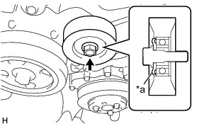
5. INSTALL NO. 2 IDLER PULLEY SUB-ASSEMBLY
(a) Install the washer plate to the No. 2 idler pulley sub-assembly as shown in the illustration.


(b) Install the washer plate and No. 2 idler pulley sub-assembly with the bolt.
Torque : 36 Nm (367 kgf-cm, 27 ft-lbf)
6. INSTALL OIL LEVEL DIPSTICK GUIDE
(a) Install a new O-ring to the oil level dipstick guide.
(b) Apply a light coat of engine oil to the O-ring.
(c) Install the oil level dipstick guide with the bolt.
Torque : 6.4 Nm (65 kgf-cm, 57 in-lbf)
(d) Install the oil level dipstick sub-assembly.
7. CONNECT ENGINE WIRE
(a) Connect the camshaft position sensor connector and camshaft timing oil control valve connector.
(b) Engage the wire harness clamp.
(c) Connect the engine oil pressure switch connector and engine oil temperature sensor connector.
(d) Connect the camshaft position sensor connector and camshaft timing oil control valve connector.
(e) Connect the 2 camshaft position sensor connectors and camshaft timing oil control valve connector.
(f) Connect the camshaft position sensor connector.
(g) Install the wire harness bracket with the bolt.
Torque : 6.4 Nm (65 kgf-cm, 57 in-lbf)
(h) Engage the wire harness clamp.
(i) Install the 2 wire harness brackets with the 2 bolts.
Torque : 6.4 Nm (65 kgf-cm, 57 in-lbf)
8. INSTALL INJECTOR COVER (for Bank 1) Installation
9. INSTALL CRANKSHAFT PULLEY Installation
10. INSTALL WATER PUMP PULLEY Installation
11. CONNECT RADIATOR OUTLET HOSE Installation
12. INSTALL EXHAUST MANIFOLD
Installation
13. INSTALL WATER FILLER SUB-ASSEMBLY Installation
14. INSTALL RADIATOR RESERVE TANK ASSEMBLY Installation
15. INSTALL INJECTOR DRIVER Installation
16. INSTALL GENERATOR ASSEMBLY
Installation
17. ADD ENGINE COOLANT
18. ADD ENGINE OIL Replacement
19. INSPECT FOR ENGINE OIL LEAK Replacement
20. CHECK ENGINE OIL LEVEL Testing and Inspection