Removal
FA20 ENGINE MECHANICAL: ENGINE UNIT: REMOVAL; 2013 MY FR-S [03/2012 -]
CAUTION:
* The exhaust valve is encapsulated with metallic sodium. The metallic sodium is a strong alkaline and prone to cause a serious chemical reaction. Therefore, extra caution is required when handling or disposing the exhaust valve.
* Never disassemble the exhaust valve. The metallic sodium may cause blindness if it gets into your eyes, or cause burn injuries or chemical reactions resulting in fire if it comes into contact with your skin or any heat source.
* If the exhaust valve is damaged, after removing the valve, carry out processing of "Preparation for disposal" and "Disposal".
* Make sure to wear safety glasses and protective gloves when removing a damaged exhaust valve.
* Do not intentionally damage the exhaust valve to remove the metallic sodium.
NOTICE:
When it is determined that disposal procedure is dissolving, this may be performed.
HINT
* The exhaust valve is encapsulated with metallic sodium. This is safe as long as it does not come into contact with air.
* The exhaust valve in which metallic sodium is encapsulated can be identified with the embossed mark.


* For removal of the exhaust valve, Disassembly.
* For disposal of the exhaust valve, Disassembly.
1. REMOVE ENGINE HANGERS
(a) Remove the bolt and engine hanger.
2. REMOVE GENERATOR COVER Removal
3. REMOVE BELT GENERATOR COVER Removal
4. REMOVE FAN AND GENERATOR V BELT Removal
5. REMOVE GENERATOR ASSEMBLY
(a) Remove the 2 bolts and generator assembly.

6. REMOVE OIL LEVEL DIPSTICK GUIDE Removal
7. REMOVE NO. 2 IDLER PULLEY SUB-ASSEMBLY Removal
8. REMOVE V-RIBBED BELT TENSIONER ASSEMBLY Removal
9. REMOVE COMPRESSOR WITH MAGNET CLUTCH Removal
10. REMOVE INJECTOR COVER (for Bank 2)
(a) Remove the 2 bolts and injector cover.

11. REMOVE INJECTOR COVER (for Bank 1)
(a) Remove the 2 bolts and injector cover.

12. REMOVE FUEL DELIVERY PIPE SUB-ASSEMBLY

(a) Remove the bolt and disconnect the fuel delivery pipe sub-assembly.
(b) Disconnect the No. 2 fuel vapor feed hose.
(c) Remove the union bolt and gasket, and disconnect the fuel delivery pipe sub-assembly.

13. SEPARATE VENTILATION HOSE Removal
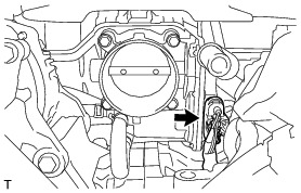
14. REMOVE INTAKE MANIFOLD
(a) Disconnect the throttle body assembly connector.
(b) Disconnect the 2 water by-pass hoses from the throttle body assembly.

(c) Disconnect the vacuum sensor connector.

(d) Disconnect the No. 1 vacuum switching valve assembly connector.

(e) Disengage the 2 clamps and disconnect the 4 connectors.


(f) Disconnect the wire harness.
(g) Disconnect the fuel pump connector.

(h) Remove the 6 bolts, intake manifold and 2 gaskets.


15. REMOVE NO. 2 FUEL DELIVERY PIPE Removal
16. REMOVE FUEL DELIVERY PIPE Removal
17. REMOVE FUEL DELIVERY PIPE LH Removal
18. REMOVE FUEL DELIVERY PIPE RH Removal
19. REMOVE FUEL INJECTOR ASSEMBLY Removal
20. REMOVE FUEL INJECTOR SEAL Removal
21. REMOVE FUEL PUMP ASSEMBLY Removal
22. REMOVE VALVE LIFTER Removal
23. REMOVE PUMP DRIVE CASE ASSEMBLY Removal
24. REMOVE ENGINE WIRE
(a) Remove the 2 bolts and separate the ground wire harness.
(b) Disconnect each connector and clamp, and remove the engine wire.
25. REMOVE NO. 2 VENTILATION HOSE
(a) Disconnect the No. 2 ventilation hose.

26. REMOVE NO. 2 WATER BY-PASS HOSE
(a) Disconnect the No. 2 water by-pass hose.

27. REMOVE NO. 3 TRANSMISSION OIL COOLER HOSE (for Automatic Transmission)
(a) Disconnect the No. 3 transmission oil cooler hose.
28. REMOVE NO. 1 WATER BY-PASS PIPE (for Manual Transmission)

(a) Loosen the hose clip and disconnect the water by-pass hose.
(b) Remove the 2 bolts and the No. 1 water by-pass pipe.
29. REMOVE NO. 1 WATER BY-PASS PIPE (for Automatic Transmission)

(a) Loosen the 2 hose clips and disconnect the 2 water by-pass hoses.
(b) Remove the 2 bolts and No. 1 water by-pass pipe.
30. REMOVE IGNITION COIL ASSEMBLY
(a) Remove the 4 bolts and 4 ignition coil assemblies.