Removal
TX6A AUTOMATIC TRANSMISSION / TRANSAXLE: AUTOMATIC TRANSMISSION ASSEMBLY: REMOVAL; 2013 MY FR-S [03/2012 -]
1. DISCONNECT CABLE FROM NEGATIVE BATTERY TERMINAL Removal
2. REMOVE NO. 1 ENGINE UNDER COVER Removal
3. REMOVE NO. 2 ENGINE UNDER COVER Removal
4. DRAIN AUTOMATIC TRANSMISSION FLUID Removal
5. REMOVE PROPELLER WITH CENTER BEARING SHAFT ASSEMBLY
Removal
6. REMOVE FRONT STABILIZER BAR
Removal
7. REMOVE STARTER ASSEMBLY
Removal
8. DISCONNECT WIRING HARNESS CONNECTOR
HINT
Fix disconnected harness components with tape to keep them out of the way.
(a) Release the lock of connector (A) and disconnect the connector.
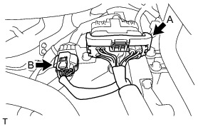
(b) Disconnect the connector (B).
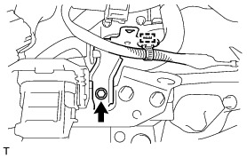
(c) Remove the bolt and disconnect the ground cable.
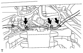
(d) Disengage the 4 wire harness clamps.
(e) Release the lock of connector (A) and disconnect the connector.
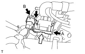
(f) Disconnect the connector (B) and (C).
(g) Disengage the wire harness clamp.
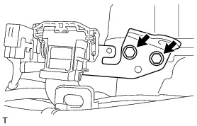
(h) Remove the bolt and the wire harness clamp bracket.
(i) Remove the 2 bolts and the No. 2 engine hanger.
9. DISCONNECT VACUUM TUBE CONNECTOR HOSE
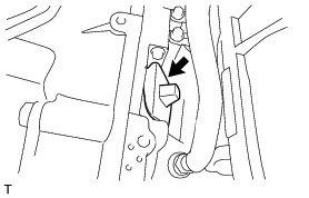
(a) Remove the 2 bolts and the disconnect the union to check valve hose.
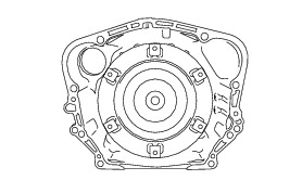
10. REMOVE FLYWHEEL HOUSING UNDER COVER
(a) Remove the flywheel housing side cover from the automatic transmission assembly.
11. REMOVE DRIVE PLATE AND TORQUE CONVERTER SETTING BOLT
(a) Using SST, hold the crankshaft pulley.
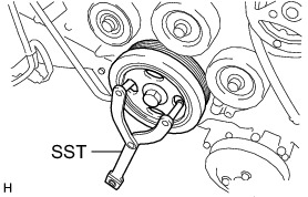
SST : 09960-10010
09962-01000
09963-01000
(b) Remove the 6 drive plate and torque converter setting bolt.
12. DISCONNECT AUTOMATIC TRANSMISSION ASSEMBLY
(a) Remove the 2 bolts from the automatic transmission assembly.
13. REMOVE EXHAUST MANIFOLD
Removal
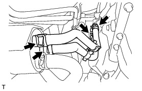
14. SUSPEND ENGINE ASSEMBLY
(a) Support the engine assembly with an engine lifter so that it is stable shown in the illustration.
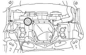
NOTICE:
* Set the engine assembly with transmission so that it is horizontal.
* Never attach the attachment and plate lift attachment to the oil pan section of the engine assembly.
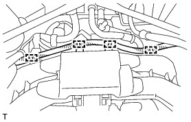
15. REMOVE TRANSMISSION OIL COOLER HOSE
(a) Loosen the 4 hose clamps and remove the 2 transmission oil cooler hoses.
NOTICE:
Use a container to catch any coolant which flows out of the transmission oil cooler hoses.
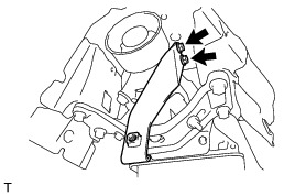
16. SEPARATE OIL COOLER TUBE
(a) Remove the 2 bolts and separate the oil cooler tube.
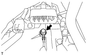
17. REMOVE TRANSMISSION REVOLUTION SENSOR (NT) Removal
18. REMOVE FLOOR SHIFT GEAR SHIFTING ROD SUB-ASSEMBLY
(a) While pushing the shift lock release button, move the shift lever to N.
(b) Remove the clip, pin and the floor shift gear shifting rod sub-assembly from the transmission control shaft lever RH.

(c) Remove the nut and disconnect the floor shift gear shifting rod sub-assembly.
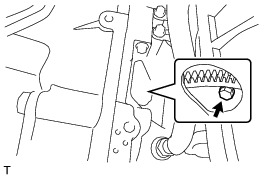
19. REMOVE EXHAUST PIPE BRACKET
(a) Remove the 2 bolts and the exhaust pipe bracket from the automatic transmission assembly.
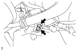
20. SUPPORT AUTOMATIC TRANSMISSION ASSEMBLY
(a) Support the automatic transmission assembly with a high transmission jack.
NOTICE:
To prevent damage to and deformation of the oil pan, never place a jack under the oil pan area of the automatic transmission assembly.
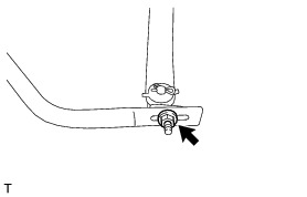
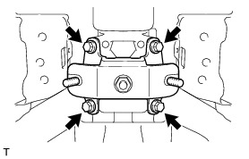
21. REMOVE REAR NO. 2 ENGINE MOUNTING INSULATOR
(a) Remove the 4 bolts, 2 washers and 2 nuts and the rear No. 2 engine mounting insulator from the rear No. 1 engine mounting insulator.
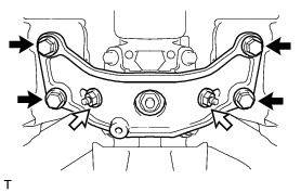
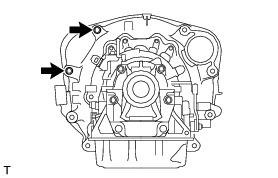
22. REMOVE REAR NO. 1 ENGINE MOUNTING INSULATOR
(a) Remove the 4 bolts and the rear No. 1 engine mounting insulator from the automatic transmission assembly.
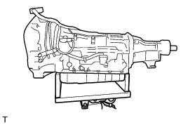
23. REMOVE AUTOMATIC TRANSMISSION ASSEMBLY
(a) Remove the 2 bolts and 2 nuts and the automatic transmission assembly from the engine assembly.
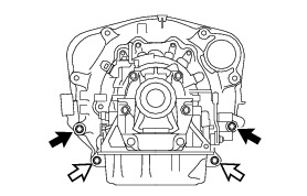

NOTICE:
* To prevent damage to the knock pins, do not pry between the automatic transmission assembly and the engine assembly.
* Do not allow the torque converter to fall off.
24. DISCONNECT WIRE HARNESS
(a) Disconnect the park/neutral position switch connector, transmission wire connector and the transmission revolution sensor connector.
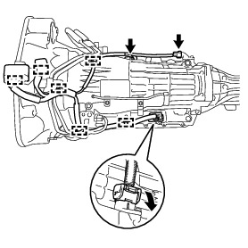
HINT
Disengage the claw, press down the lever, and disconnect the transmission wire connector.
(b) Disengage the 6 wire harness clamps and the wire harness from the automatic transmission assembly.
25. REMOVE OIL COOLER TUBE
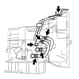
(a) Loosen the 4 hose clamps and remove the 2 oil cooler hoses.
NOTICE:
Use a container to catch any coolant which flows out of the oil cooler hoses.
(b) Remove the 2 bolts and the oil cooler tube from the automatic transmission assembly.
26. REMOVE TORQUE CONVERTER ASSEMBLY
(a) Remove the torque converter assembly from the automatic transmission assembly.
NOTICE:
Remove the torque converter assembly from the input shaft horizontally.
27. INSPECT TORQUE CONVERTER ASSEMBLY Testing and Inspection