Blower Fan
A/C Fan Switch Schematic:
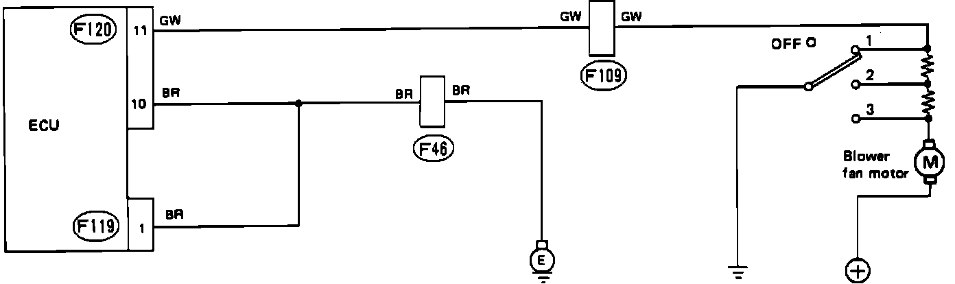
A faulty air conditioning/blower fan switch will set code 63 in the on-board diagnostic system. Refer to the schematic diagram and test the switch with the diagnostic chart.
Wire color code identification:
L: Blue
B: Black
Y: Yellow
G: Green
R: Red
W: White
Br: Brown
Lg: Light green
Gr: Gray
A/C Fan Switch Diagnostic Chart:
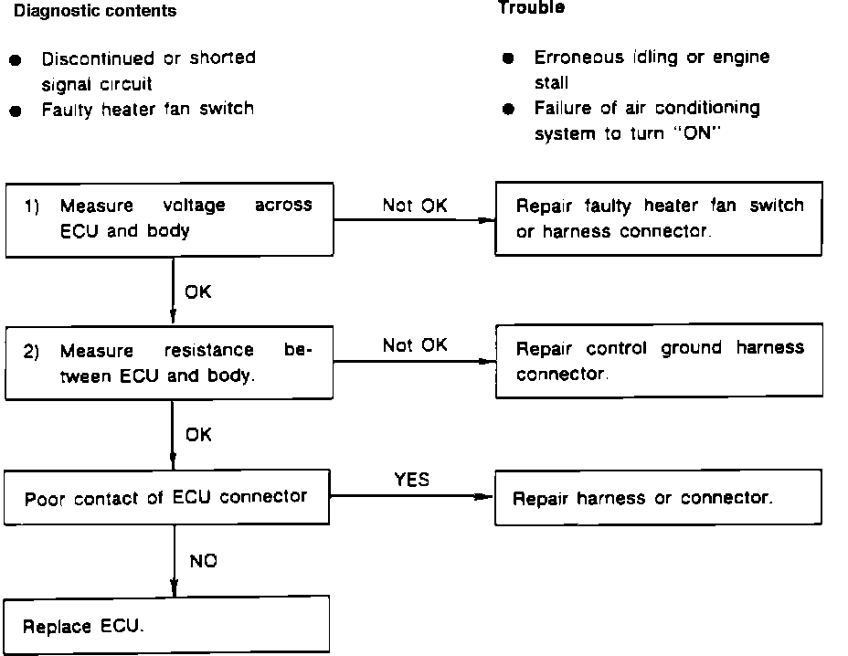
A/C AND BLOWER FAN SWITCH DIAGNOSTIC CHART
ECU Connectors:

CHECK VOLTAGE AND RESISTANCE
1. With ignition "OFF," disconnect ECU connector.
2. Measure voltage across ECU connector terminals and ground as follows:
Connector & terminal: Voltage:
(F120)11-Ground Above 8V (heater fan "OFF")
(F120)11-Ground Below 2V (heater fan 3rd speed)
2. With ignition "OFF," measure resistance between ECU connector and ground as follows:
Connector & terminal: Resistance:
(F119)1-Ground Below 10 Ohms
(F120)10-Ground Below 10 Ohms