Brake Pedal Assy: Service and Repair
ON-CAR SERVICEBrake Pedal
1) Check position of pedal pad.
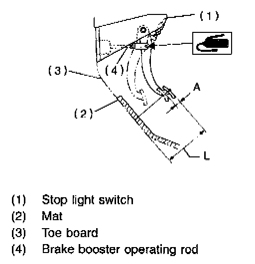
Pedal height: L
148 mm (5.83 inch)
2) If it is not in specified value, adjust it by adjusting brake booster operating rod length.
3) Check free play by operating pedal by hand. If it is not in specified value, adjust it by adjusting position of stop light switch.
CAUTION:
^ Be careful not to rotate stop light switch.
Brake pedal free play: A
1-3 mm (0.04 - 0.12 inch) [Depress brake pedal/pad with a force of less than 10 N (1 kg, 2 lb).]
Stop light switch lock nut tightening torque:
8 ± 2 Nm (0.8 ± 0.2 kg-m, 5.8 ± 1.4 ft. lbs.)
4) Apply grease to operating rod connecting pin to prevent it from wearing.
Clutch Pedal
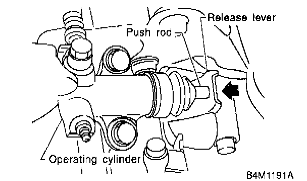
1) Push release fork until operating cylinder push rod retracts. Check that clutch fluid level in reservoir tank increases.
2) If clutch fluid level increases, hydraulic clutch play is correct.
3) If clutch fluid level does not increase or push rod does not retract, clutch pedal must be adjusted.
4) Check the fluid level on the outside of the clutch master cylinder tank. If the level is below "MIN". add clutch fluid to bring it up to "MAX".
Recommended clutch fluid:
FMVSS No. 11fi fresh DOT 3 or DOT 4 brake fluid
Accelerator Pedal
- Check pedal stroke and free play by operating accelerator pedal by hand. If it is not within specified value, adjust it by turning nut connecting accelerator cable to throttle body.
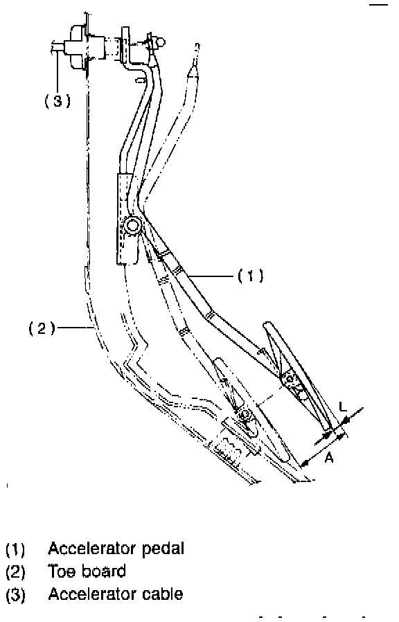
Free play at pedal pad: L
1-4 mm (0.04 - 0.16 inch)
Stroke at pedal pad: A
50 - 55 mm (1.97 - 2.17 inch)
Accelerator cab/e lock nut tightening torque:
14 ± 4 Nm (1.4 ± 0.4 kg-m, 10.1 ± 2.9 ft. lbs.)
REMOVAL
Accelerator Pedal
1) Disconnect ground cable from battery.
2) Disconnect accelerator cable from throttle body.
CAUTION:
^ Be careful not to kink accelerator cable.
3) Remove instrument panel lower cover from instrument panel, and connector.
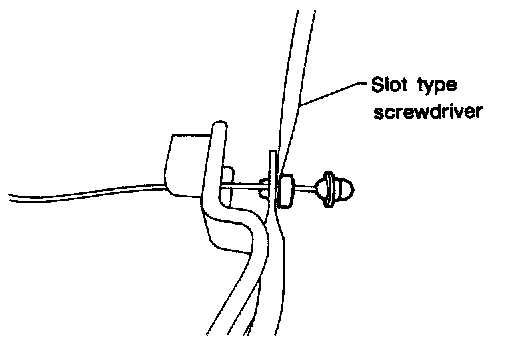
4) Disconnect accelerator cable from accelerator pedal lever.
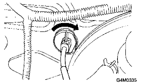
5) Working inside engine compartment, remove casing cap out of the toe board by turning it clockwise.
6) Pull out the cable from the toe board hole.
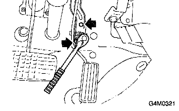
7) Remove accelerator pedal connecting bolt from accelerator pedal bracket.
Brake And Clutch Pedal
1) Disconnect ground cable from battery.
2) Remove instrument panel lower cover from instrument panel.
3) Disconnect the following parts from pedal bracket.
- Operating rod of brake booster
- Electrical connectors (for stop light switch, etc.)
4) Remove clevis pin which secures lever to push rod.
5) Remove nut which secures clutch master cylinder.
6) Remove bolts and nuts which secure brake and clutch pedals, and remove pedal assembly.
Brake Pedal
1) Disconnect ground cable from battery.
2) Remove instrument panel lower cover from instrument panel.
3) Remove clevis pin which secures brake pedal to brake booster operating rod. Also disconnect stop light switch connector.

4) Remove two bolts and four nuts which secure brake pedal to pedal.
INSPECTION
Brake And Clutch Pedals
- Move brake and clutch pedal pads in the lateral direction with a force of approximately 10 N (1 kg, 2 lb) to ensure pedal deflection is in specified range.
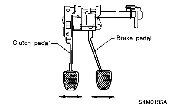
Deflection of brake and clutch pedal:
Service limit
5.0 mm (0.197 inch) or less
CAUTION:
^ If excessive deflection is noted, replace bushings with new ones.
Accelerator Pedal
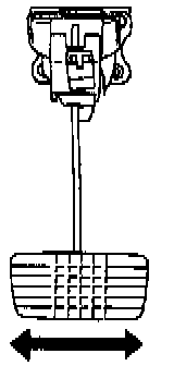
- Lightly move pedal pad in lateral the direction to ensure pedal deflection is in specified range.
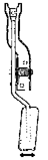
Deflection of accelerator pedal:
Service limit 5.0 mm (0.197 inch) or less
CAUTION:
^ If excessive deflection is noted, replace bushing and clip with new ones.
Stop Light Switch
- If stop light switch does not operate properly (or if it does not stop at the specified position), replace with a new one.
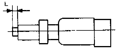
Specified position: L
2.8 +1.5/0 mm (0.110 +0.059/0 inch)
ASSEMBLY
Brake And Clutch Pedal
1) Attach stop light switch, etc. to pedal bracket temporarily.
2) Clean inside of bores of clutch pedal and brake pedal apply grease, and set bushings into bores.
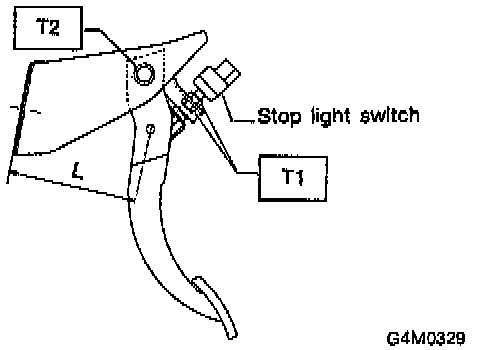
3) Align bores of pedal bracket, clutch pedal and brake pedal, attach brake pedal return spring and clutch pedal effort reducing spring (vehicle with hill holder), and then install pedal bolt.
Tightening torque:
T2: 29 ± 7 Nm (3.0 ± 0.7 kg-m, 21.7 ± 5.1 ft. lbs.)
NOTE:
- Clean up inside of bushings and apply grease before installing spacer.
4) Set brake pedal position by adjusting position of stop light switch.
Pedal position: L
125.9 mm (4.96 inch)
Tightening torque:
T1: 8 ± 2 Nm (0.8 ± 0.2 kg-m, 5.8 ± 1.4 ft. lbs.)
Accelerator Pedal
- Clean and apply grease to spacer and inside bore of accelerator pedal. Install accelerator pedal onto pedal bracket.
INSTALLATION
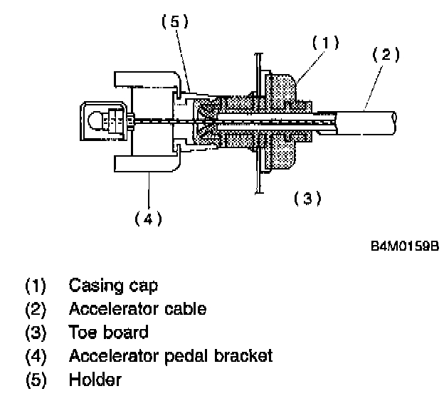
1) Installation is in the reverse order of removal procedures.
CAUTION:
^ Be careful not to bend clutch cable too much.
^ Never fail to cover outer cable end with boot.
^ Be careful not to kink accelerator cable.
^ Make sure that holder and casing cap are securely connected.
2) Adjust clutch pedal.
3) Adjustment after pedal installation
ADJUSTMENT
Clutch Pedal
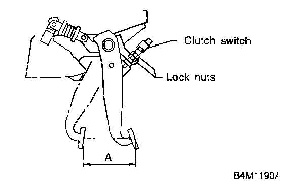
1) Turn cruise control clutch switch lock nuts until clutch pedal full stroke length is within specifications.
CAUTION:
^ Do not attempt to turn clutch switch to adjust clutch pedal full stroke length.
NOTE:
- If lock nuts cannot adjust clutch pedal full stroke length to specifications, turn master cylinder push rod to adjust it.
Specified clutch pedal full stroke: A
130 - 135 mm (5.11 - 5.31 inch)
Tightening torque (Clutch switch lock nut):
8 ± 2 Nm (0.8 ± 0.2 kg-m, 5.8 ± 1.4 ft. lbs.)
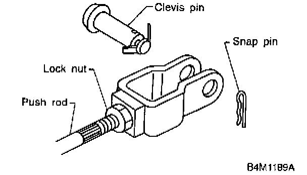
2) Turn master cylinder push rod so that clevis pin moves to the left and then to the right. Clevis pin must move without resistance while it is rattling.
Tightening torque (Push rod lock nag):
8 ± 2 Nm (0.8 ± 0.2 kg-m, 5.8 ± 1.4 ft. lbs.)
3) Depress and release clutch pedal 2 to 3 times to ensure that clutch pedal and release fork operate smoothly. If clutch pedal and release fork do not operate smoothly, bleed air from clutch hydraulic system.
4) Measure clutch pedal full stroke length again to ensure that it is within specifications. If it is not, repeat adjustment procedures again from the beginning.
Specified clutch pedal full stroke:
130 - 135 mm (5.11 - 5.31 inch)
5) Move clevis pin to the left and then to the right. It should move without resistance while it is rattling. If resistance is felt' repeat adjustment procedures again from the beginning.
6) Push release lever until operating cylinder push rod retracts. Ensure that clutch fluid level in reservoir tank increases. If clutch fluid level increases, hydraulic clutch is properly adjusted; if fluid level does not increase or push rod does not retract, replace master cylinder with new one.