Inspection of ECM and Its Circuits 3
Inspection of ECM and Its Circuits26. Reference waveform No. 26
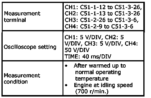
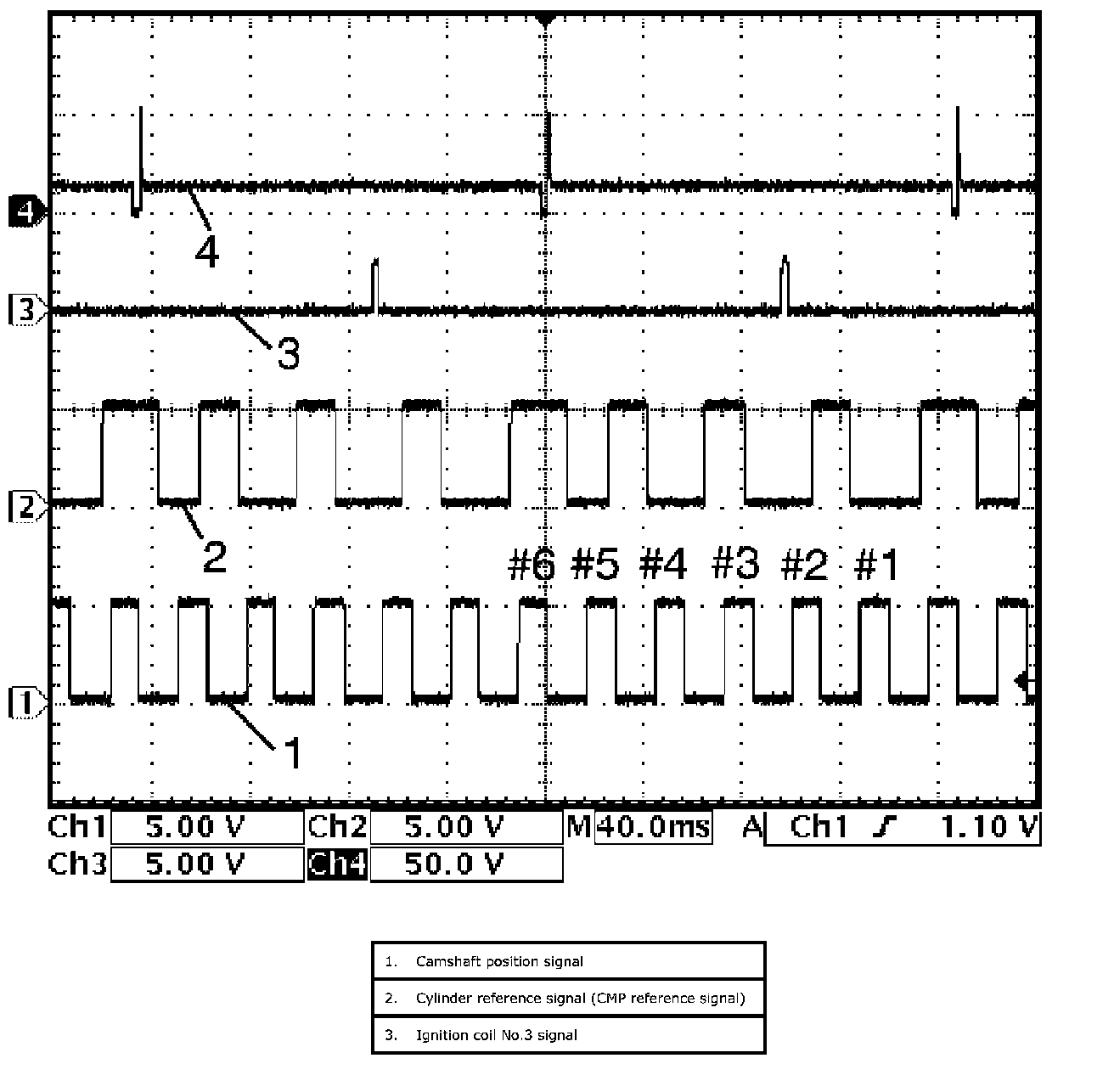
Fuel injector No.3 signal (4) at engine idling
27. Reference waveform No. 27
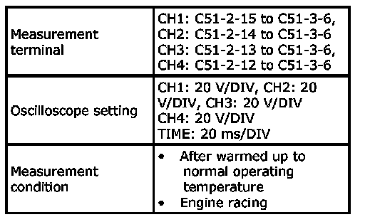
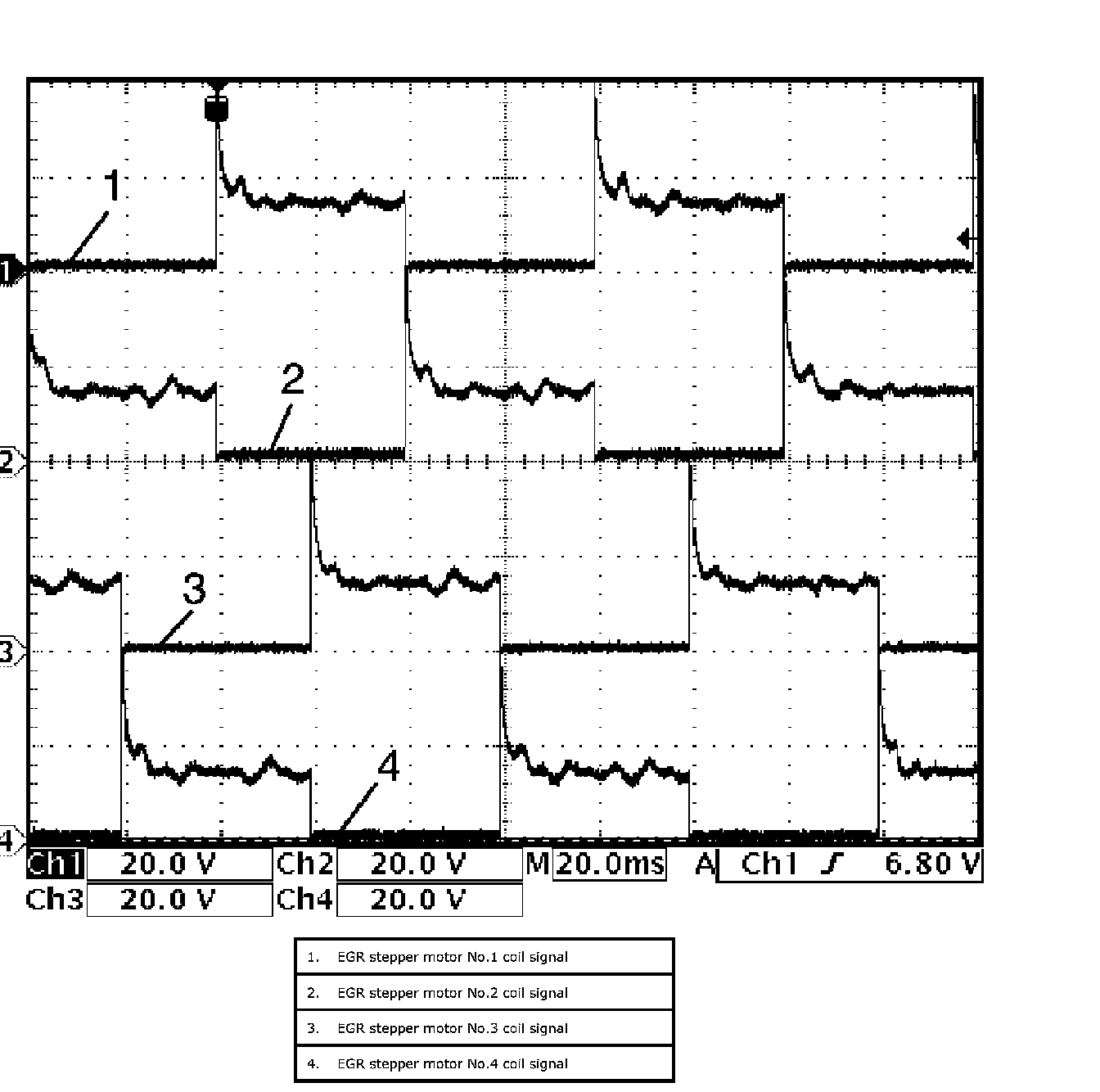
EGR valve signal at engine racing
28. Reference waveform No. 28
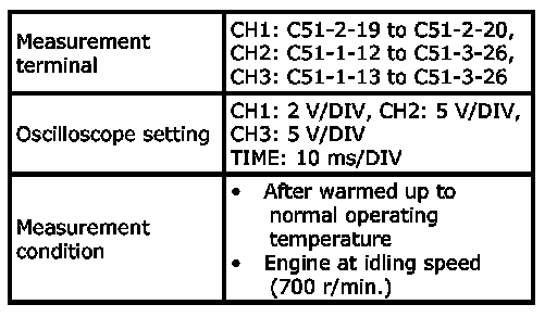
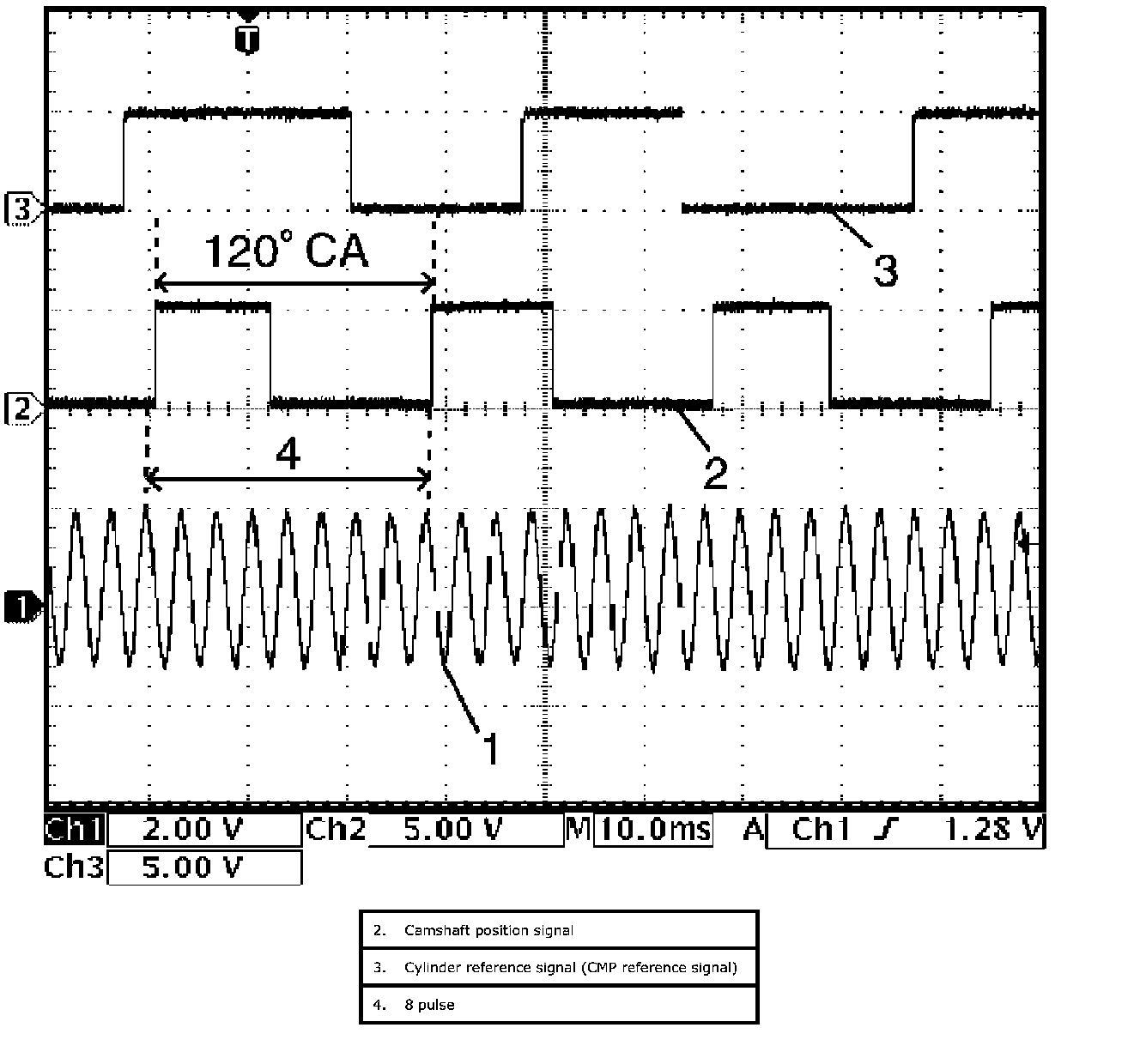
CKP sensor signal (1) at engine idling
29. Reference waveform No. 29
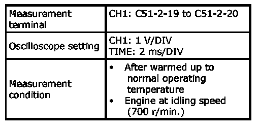
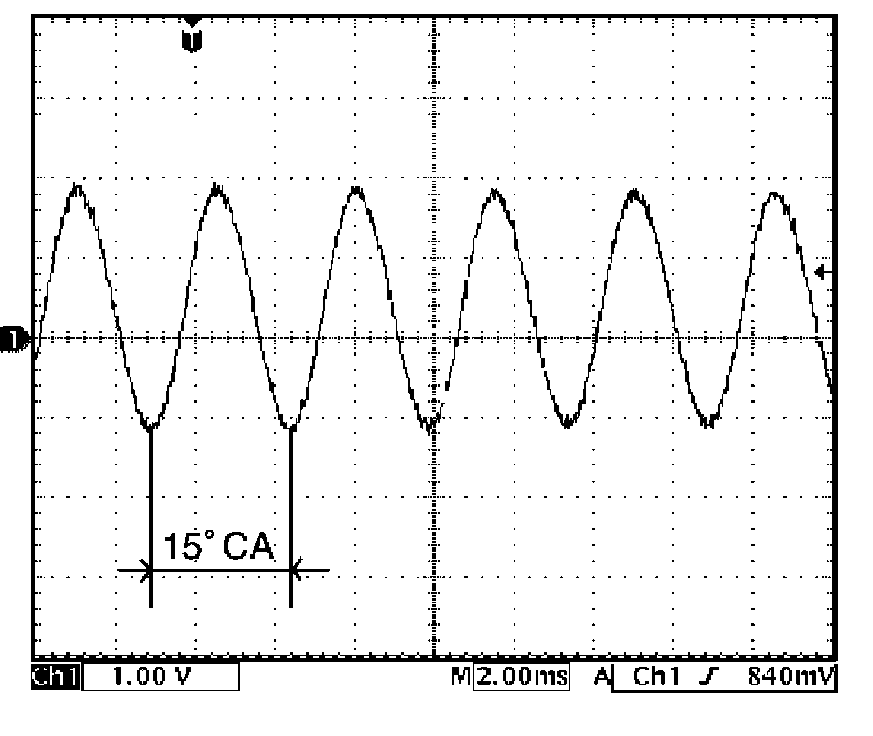
CKP sensor signal at engine idling
30. Reference waveform No. 30
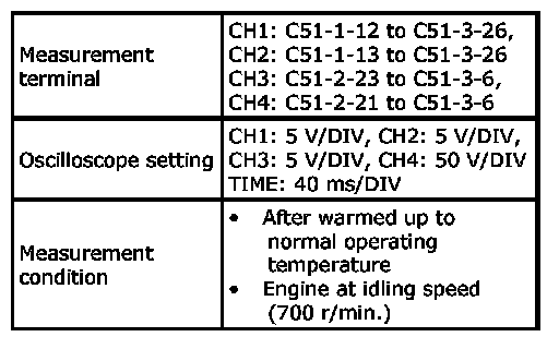
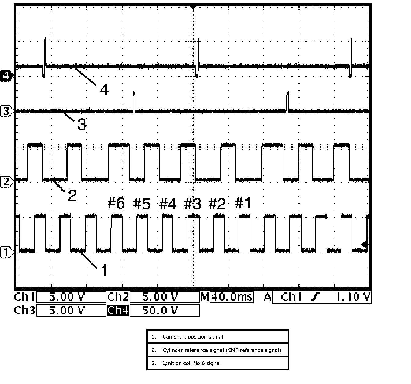
Fuel injector No.6 signal (4) at engine idling
31. Reference waveform No. 31
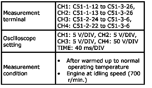
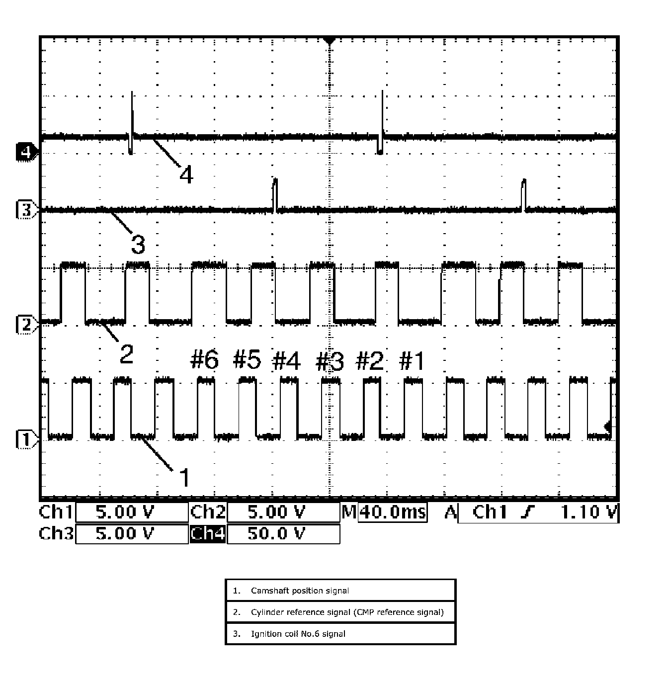
Fuel injector No.5 signal (4) at engine idling
32. Reference waveform No. 32
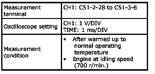
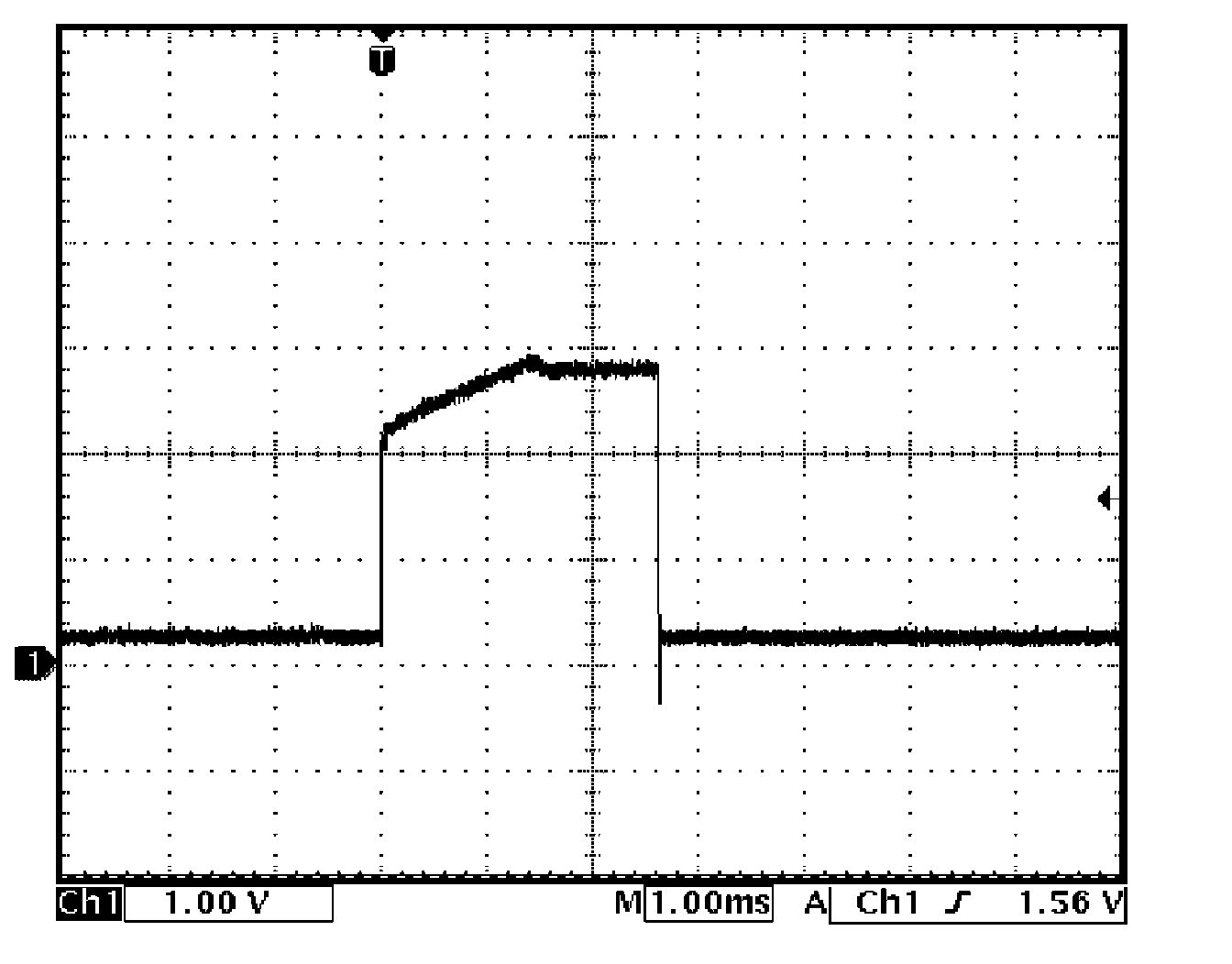
Ignition coil signal at engine idling
33. Reference waveform No. 33
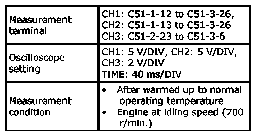
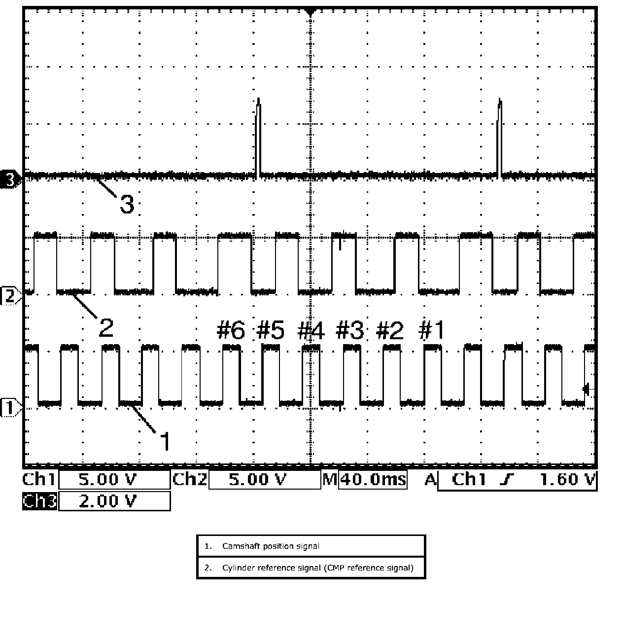
Ignition coil No.6 signal (3) at engine idling
34. Reference waveform No. 34
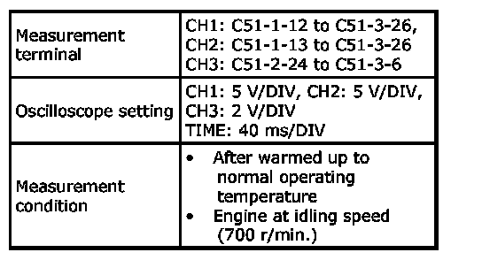
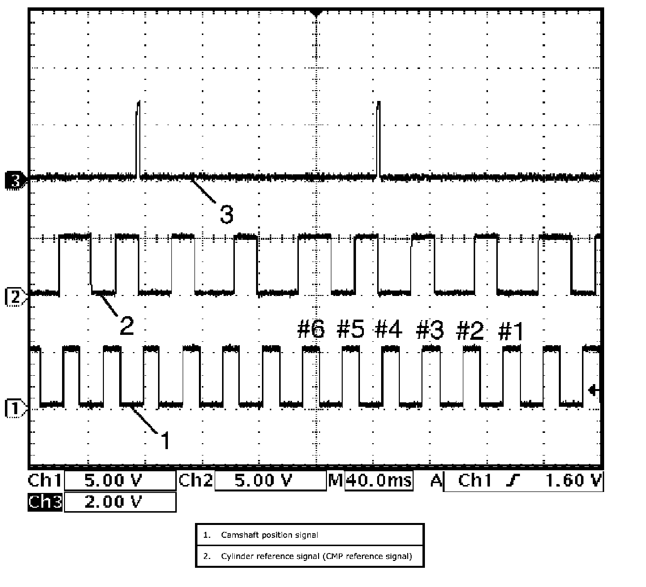
Ignition coil No.5 signal (3) at engine idling
35. Reference waveform No. 35
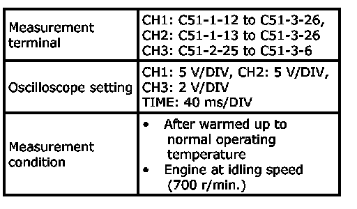
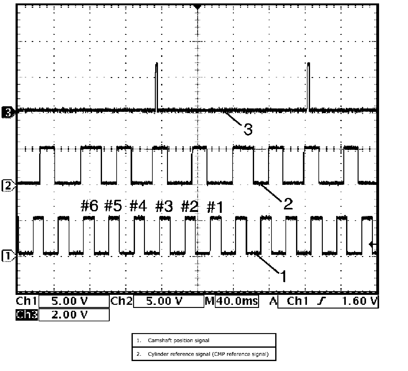
Ignition coil No.4 signal (3) at engine idling
36. Reference waveform No. 36
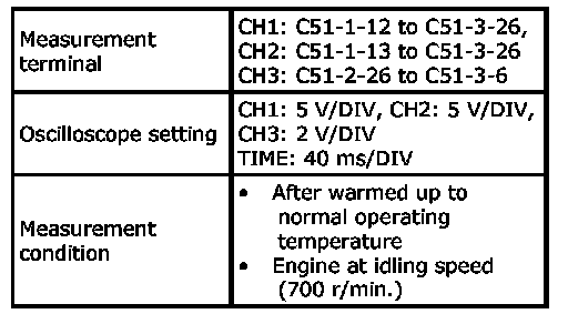
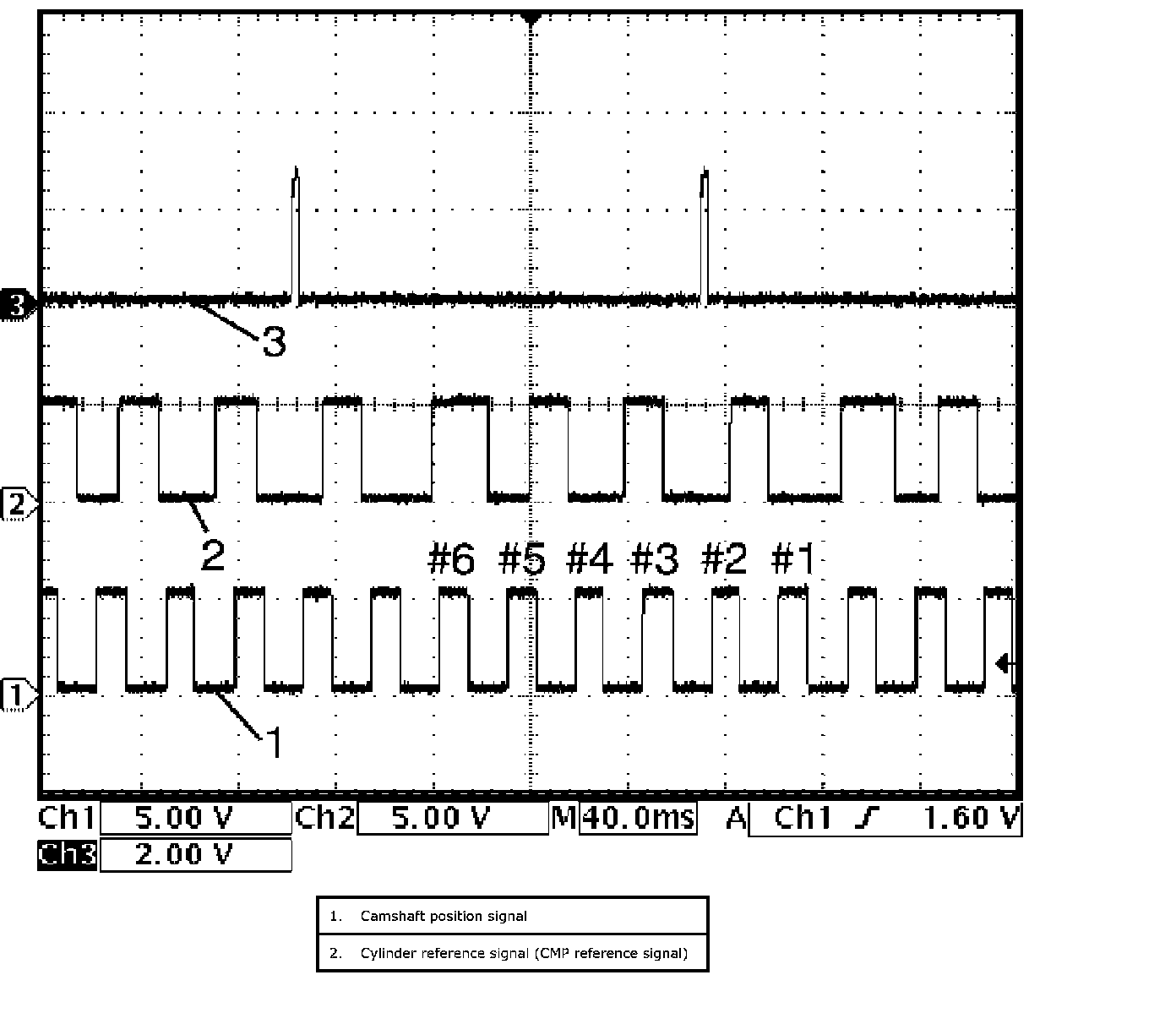
Ignition coil No.3 signal (3) at engine idling
37. Reference waveform No. 37
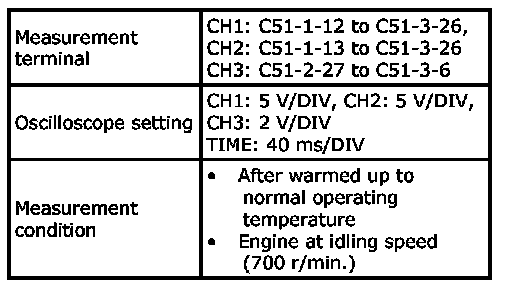
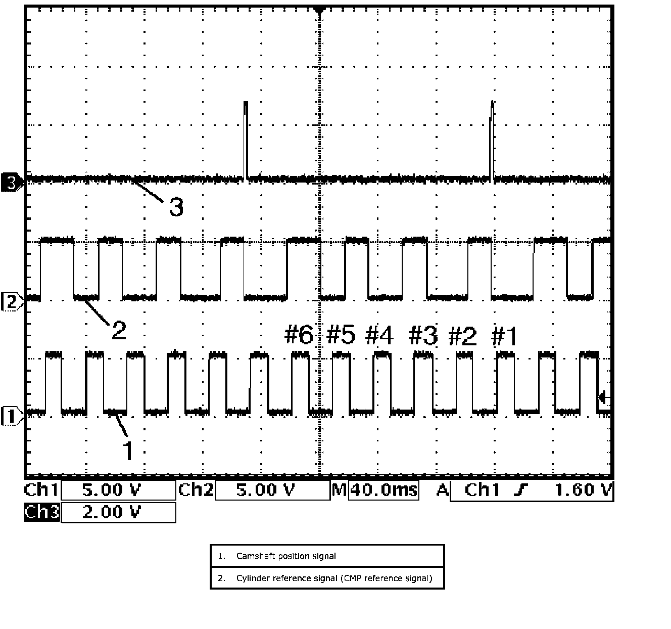
Ignition coil No.2 signal (3) at engine idling
38. Reference waveform No. 38
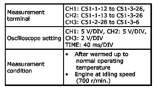

Ignition coil No.1 signal (3) at engine idling
Resistance Check
Ter. C51-3-7 - C51-3-4:
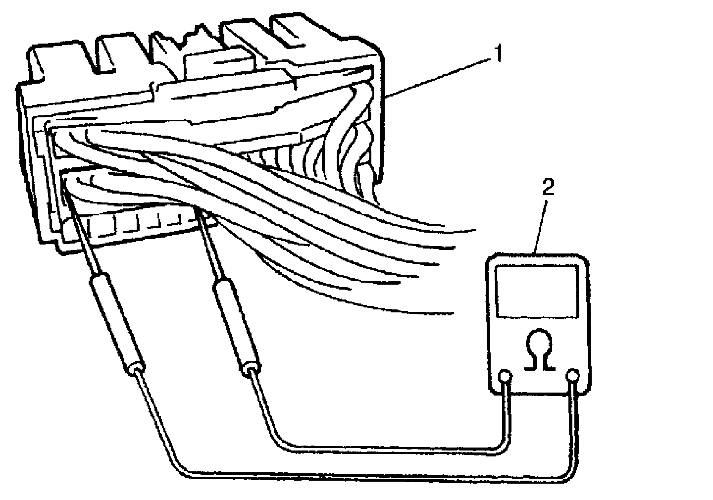
1. Disconnect couplers (1) from ECM with ignition switch OFF.
CAUTION: Never touch terminals of ECM itself or connect voltmeter or ohmmeter (2).
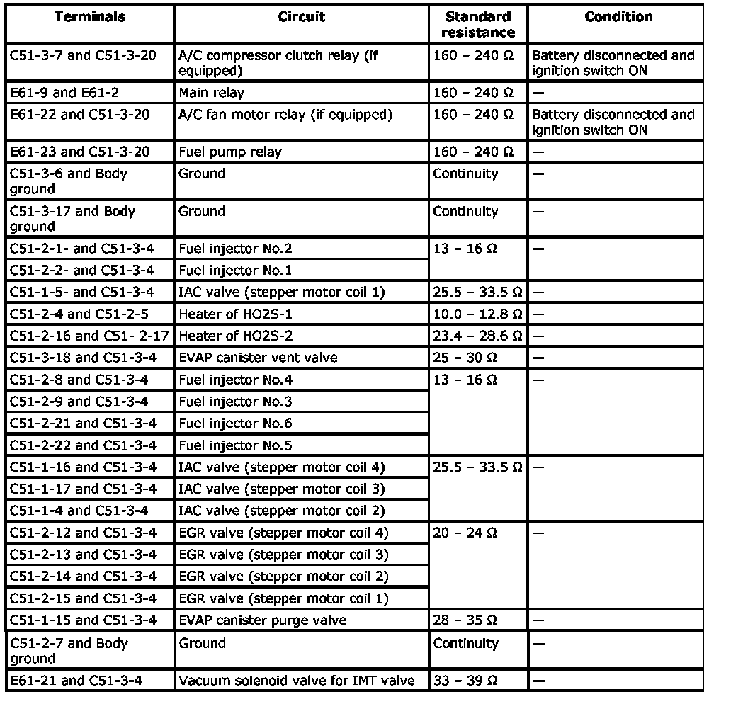
2. Check resistance between each pair of terminals of disconnected couplers (1) as listed in the following table.
CAUTION:
- Be sure to connect ohmmeter (2) probe from wire harness side of coupler.
- Be sure to turn OFF ignition switch for this check.
- Resistance in table represents that when parts temperature is 20 degrees C (68 degrees F).