Partial Engine Assembly Replacement
Part 1 Of 10:

Part 2 Of 10:

Part 3 Of 10:

Part 4 Of 10:

Part 5 Of 10:

Part 6 Of 10:

Part 7 Of 10:

Part 8 Of 10:

Part 9 Of 10:

Part 10 Of 10:

REPLACEMENT
1. WORK FOR PREVENTING GASOLINE FROM SPILLING OUT
2. REMOVE AUTOMATIC TRANSMISSION ASSY (2WD DRIVE TYPE)
3. REMOVE AUTOMATIC TRANSMISSION ASSY (4WD DRIVE TYPE)
4. REMOVE HOOD SUB-ASSY
a. Disconnect the windshield washer hose.
b. Remove the 4 nuts, and hood sub-assy.
5. REMOVE THROTTLE BODY COVER SUB-ASSY
a. Remove the 2 cap nuts and throttle body cover sub-assy.
6. REMOVE AIR CLEANER HOSE ASSY
a. Disconnect the vacuum hoses (For P/S idle up and for fuel pressure regulator) and ventilation hose.
7. REMOVE AIR CLEANER ASSY
a. Disconnect the intake air flow meter connector.
b. Remove the air cleaner cap and air cleaner element.
c. Remove the 3 bolts and air cleaner assy.
8. REMOVE ENGINE UNDER COVER SUB-ASSY No.1
9. REMOVE ENGINE UNDER COVER ASSY REAR
10. DRAIN ENGINE COOLANT
11. DRAIN ENGINE OIL
a. Remove the oil pan drain plug and drain the engine oil.
b. Clean the oil pan drain plug and install a new gasket and it.
Torque: 39 Nm (398 kgf-cm, 29 ft. lbs.)
12. REMOVE RADIATOR ASSY
13. REMOVE FAN SHROUD
a. Disconnect the fasteners of clamp and oil cooler hoses from fan shroud in sequence.
b. Remove the fun shroud with fan.
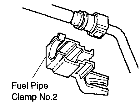
14. DISCONNECT FUEL HOSE No.2
a. Observe these precautions when disconnecting the fuel tube connector.
1. Remove the fuel pipe clamp No.2.
2. Check if there is any dirt like mud on the pipe and around the connector before disconnecting them and clean the dirt away.
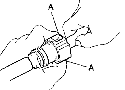
3. Disconnect the connector from the hose while pinching part A with fingers as shown in the illustration.
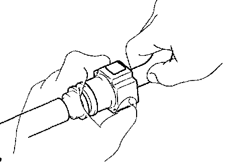
4. When the connector and the pipe are stuck, pinch the fuel pipe between the hands, push and pull the connector to free to disconnect and pull it out. Do not use any tool at this time.
5. Inspect if there is any dirt or the likes on the seal surface of the disconnected pipe and clean it away.
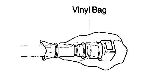
6. Prevent the disconnected pipe and connector from damaging and mixing foreign objects by covering them with a vinyl bag.
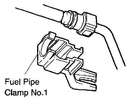
15. DISCONNECT FUEL HOSE
a. Observe these precautions when disconnecting the fuel tube connector.
1. Remove the fuel pipe clamp No.1.
2. Check if there is any dirt like mud on the pipe and around the connector before disconnecting them and clean the dirt away.
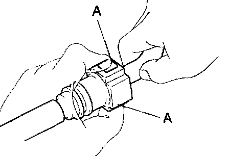
3. Disconnect the connector from the hose white pinching part A with fingers as shown in the illustration.
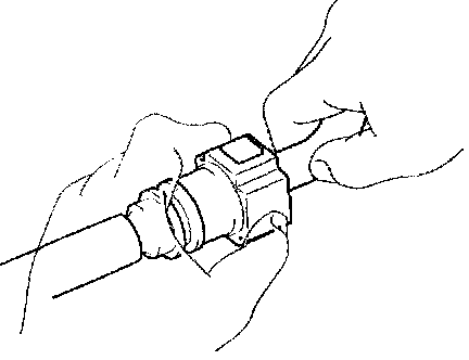
4. When the connector and the pipe are stuck, pinch the fuel pipe between the hands, push and pull the connector to free to disconnect and pull it out. Do not use any tool at this time.
5. Inspect if there is any dirt or the likes on the seal surface of the disconnected pipe and clean it away.
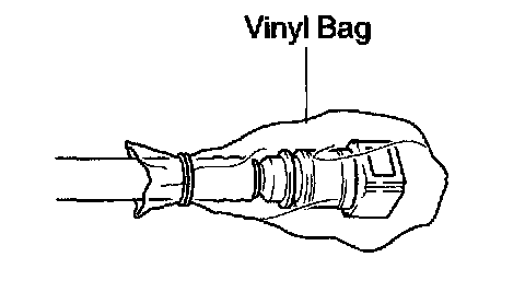
6. Prevent the disconnected pipe and connector from damaging and mixing foreign objects by covering them with a vinyl bag.
16. DISCONNECT FUEL VAPOR FEED HOSE ASSY
17. REMOVE FAN AND GENERATOR V BELT
18. SEPARATE VANE PUMP ASSY
a. Disconnect the vacuum hose.
b. Remove the nut, 2 bolts and vane pump assy.
HINT: Hang up the hose instead of detaching.
19. REMOVE GENERATOR ASSY
20. SEPARATE COMPRESSOR
Remove the nut, 3 bolts, compressor stay and compressor.
HINT: Hang up the hoses instead of detaching.
21. REMOVE FAN W/ FLUID COUPLING
a. Remove the 4 nuts and fan w/ fluid coupling.
b. Remove the fan pulley.
22. REMOVE TRANSMISSION OIL FILLER TUBE SUB-ASSY
a. Remove the bolt, and transmission oil filler tube.
23. REMOVE OIL LEVEL GAGE GUIDE
a. Remove the bolt, and oil level gage guide.
24. REMOVE EXHAUST MANIFOLD SUB-ASSY RH
a. Remove the 4 bolts and exhaust manifold heat insulator No.1.
b. Disconnect the oxygen sensor connector.
c. Remove the 8 nuts and exhaust manifold sub-assy.
25. REMOVE EXHAUST MANIFOLD SUB-ASSY LH
a. Remove the 4 bolts and exhaust manifold heat insulator No.2.
b. Disconnect the oxygen sensor connector.
c. Remove the 8 nuts and exhaust manifold sub-assy.
27. SEPARATE ENGINE WIRE
a. Remove the front door scuff plate RH.
b. Remove the cowl side trim board RH.
c. Remove the glove compartment door.
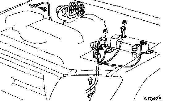
d. Disconnect each connector for the ECM, four wheel drive control ECU (4WD only) and instrument panel wire before pull out the engine wire into the engine room.
e. Disconnect the 3 ground cables from the body.
f. Disconnect the engine wire No.2 from the battery terminals (positive and negative) and engine room relay block.
28. REMOVE ENGINE ASSY
a. Attach the engine chain hoist to the engine hangers.
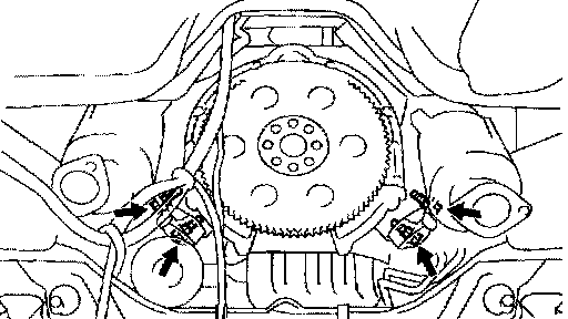
b. Remove the 4 nut's and 4 bolt's.
c. Lift the engine out of the vehicle slowly and carefully
HINT: Make sure the engine is clear of all wiring hose and cable.
29. REMOVE ENGINE WIRE
a. Disconnect the VSV connector.
b. Disconnect the solenoid connector.
30. REMOVE INTAKE MANIFOLD ASSY
a. Remove the 6 bolts and 4 nuts.
b. Remove the intake manifold assy and 2 gaskets.
31. REMOVE WIRING HARNESS HEAT INSULATOR No.2
a. Remove the 2 bolt's and wiring harness heat insulator No.2.
32. REMOVE ENGINE WIRE No.2
a. Separate the ground cable wire clamp.
b. Remove the 3 bolts and engine wire No.2.
33. REMOVE ENGINE MOUNTING BRACKET FRONT No.1 RH
a. Remove the 4 bolts and engine mounting bracket together with engine mounting insulator.
34. REMOVE ENGINE MOUNTING BRACKET FRONT No.1 LH
a. Remove the 4 bolts and engine mounting bracket together with engine mounting insulator.
35. REMOVE HEATER HOSE
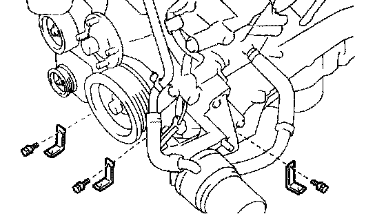
36. REMOVE HARNESS BRACKET
a. Remove the 3 bolt's and 3 wire harness bracket.
37. REMOVE DRIVE PLATE & RING GEAR SUB-ASSY
38. REMOVE OIL COOLER PIPE
a. Disconnect the 3 hoses.
b. Remove the bolt nut and oil cooler pipe.
39. REMOVE PUMP BRACKET
a. Remove the 4 bolts and pump bracket.
40. REMOVE TIMING BELT COVER SUB-ASSY No.3 LH
a. Remove the grommet and separate the cam position sensor connector from timing belt cover sub assy No.3 LH.
b. Remove the 4 bolts and timing belt cover sub-assy No.3 LH.
41. REMOVE TIMING CHAIN OR BELT COVER No.2
a. Remove the nut, 3 bolts and timing belt cover No.2.
42. REMOVE TIMING BELT COVER SUB-ASSY No.2
a. Remove the 2 bolts and timing belt cover sub-assy No.2.
43. REMOVE V-RIBBED BELT TENSIONER ASSY
a. Remove the bolt 2 nuts and v-ribbed belt tensioner.
44. REMOVE FAN BRACKET SUB-ASSY
a. Remove the 2 nuts, 2 bolts and fan bracket sub-assy with fan pulley.
45. REMOVE IGNITION COIL ASSY
a. Remove the 8 bolts and 8 ignition coil assy's.
46. REMOVE CAMSHAFT POSITION SENSOR
a. Remove the bolt, stud bolt and camshaft position sensor.
47. REMOVE CRANKSHAFT POSITION SENSOR
a. Remove the bolt and crankshaft position sensor.
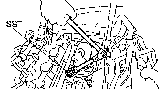
48. REMOVE KNOCK CONTROL SENSOR
a. Using a SST, remove the 2 knock control sensors.
SST 09810-30010
49. REMOVE WATER BY-PASS JOINT RR
a. Remove the 4 nuts and water by pass joint.
50. REMOVE STARTER ASSY
a. Disconnect the engine wire No.2.
b. Remove the 2 bolts and starter assy.
51. REMOVE WATER BY-PASS PIPE SUB-ASSY
a. Remove the bolt and water by-pass.
52. REMOVE WATER INLET HOUSING
53. REMOVE WATER BY-PASS JOINT FR
a. Remove the 4 nuts, water by-pass and 2 gaskets.
54. REMOVE OIL COOLER ASSY
a. Remove the 2 bolts and nut.
b. Remove the oil cooler assy w/ bracket and gasket.
55. REMOVE VENTILATION VALVE SUB-ASSY
56. REPLACE PARTIAL ENGINE ASSY
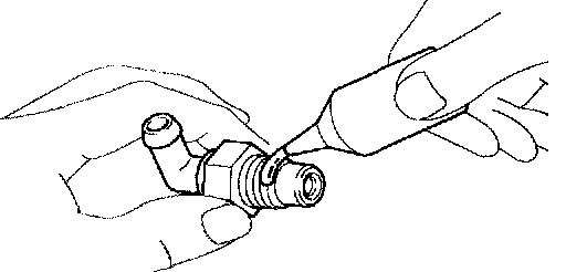
57. INSTALL VENTILATION VALVE SUB-ASSY
a. Apply adhesive to 2 or 3 threads.
Adhesive: Part No. 08833-00070, THREE BOND 1324 or equivalent
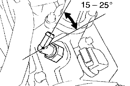
b. Install the PCV valve.
Torque: 27 Nm (275 kgf-cm, 20 ft. lbs.)
HINT: After applying the specified torque, rotate PCV valve clockwise with the port faced in the direction indicated in the illustration.
c. Install the PCV valve cover to the PCV valve.
d. Connect the PCV hose to the PCV valve.
58. INSTALL OIL COOLER ASSY
a. Place the new O-ring into the groove of oil pump.
b. Apply a light coat of engine oil on the O-ring.
c. Install the oil cooler assy with the 2 bolts and nut.
Torque:
Bolt 18 Nm (185 kgf-cm, 13 ft. lbs.)
Nut 18 Nm (185 kgf-cm, 13 ft. lbs.)
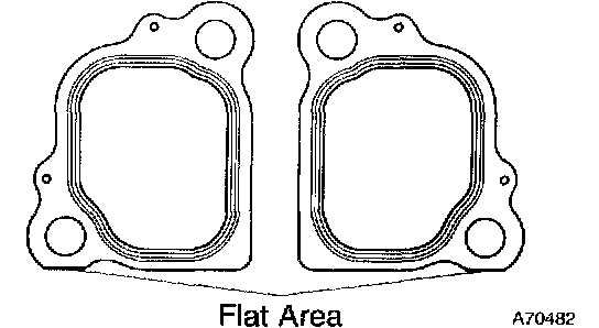
59. INSTALL WATER BY-PASS JOINT FR
a. Attach the 2 gaskets, with put the flat area of the part, shown in the illustration, to the engine front side.
b. Install the water by-pass joint with the 4 nuts.
Torque: 18 Nm (185 kgf-cm, 13 ft. lbs.)
60. INSTALL WATER INLET HOUSING
61. INSTALL WATER BY-PASS PIPE SUB-ASSY
a. Install a new O-ring to the water by-pass pipe.
b. Apply soapy water to the O-ring.
c. Push in the water by-pass pipe end into the pipe hole of the water pump.
d. Install the water by-pass pipe with the bolt.
Torque: 18 Nm (185 kgf-cm, 13 ft. lbs.)
62. INSTALL STARTER ASSY
a. Install the starter assy with 2 bolts.
Torque: 39 Nm (400 kgf-cm, 29 ft. lbs.)
b. Connect the engine wire No.2.
Torque: 9.8 Nm (100 kgf-cm. 7.2 ft. lbs.)
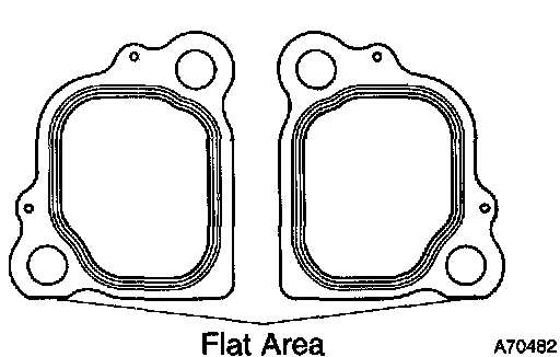
63. INSTALL WATER BY-PASS JOINT RR
a. Attach the 2 gaskets, with put the flat area of the part, shown in the illustration, to the engine rear side.
b. Install the 4 nuts holding the water bypass joint to the cylinder head. Alternately tighten the nuts.
Torque: 18 Nm (185 kgf-cm, 13 ft. lbs.)
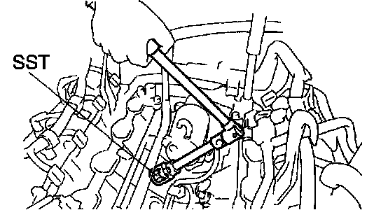
64. INSTALL KNOCK CONTROL SENSOR
a. Using a SST, install the 2 knock control sensors.
SST 09810-30010
Torque: 45 Nm (450 kgf-cm, 33 ft. lbs.)
65. INSTALL CRANKSHAFT POSITION SENSOR
a. Install the crankshaft position sensor with bolt.
Torque: 6.5 Nm (65 kgf-cm, 58 inch lbs.)
66. INSTALL CAMSHAFT POSITION SENSOR
a. Install the camshaft position sensor with bolt and stud bolt.
Torque: 7.5 Nm (80 kgf-cm, 66 inch lbs.)
67. INSTALL IGNITION COIL ASSY
a. Install the 8 ignition coils with 8 bolts.
Torque: 7.5 Nm (80 kgf-cm, 66 inch lbs.)
68. INSTALL FAN BRACKET SUB-ASSY
a. Install the fan bracket with 2 bolts and 2 nuts.
Torque:
12 mm head 16 Nm (160 kgf-cm, 12 ft. lbs.)
14 mm head 32 Nm (330 kgf-cm, 24 ft. lbs.)
69. INSTALL V-RIBBED BELT TENSIONER ASSY
a. Install the v-ribbed belt tensioner with the bolt and 2 nuts.
Torque:
Bolt 16 Nm (160 kgf-cm, 12 ft. lbs.)
Nut 16 Nm (160 kgf-cm, 12 ft. lbs.)
70. INSTALL TIMING BELT COVER SUB-ASSY No.2
a. Install timing belt cover sub-assy No.2 with the 2 bolts.
Torque: 16 Nm (160 kgf-cm, 12 ft. lbs.)
71. INSTALL TIMING CHAIN OR BELT COVER No.2
a. Install the timing chain or belt cover with the nut and 2 bolts.
Torque:
Bolt 7.5 Nm (80 kgf-cm, 66 inch lbs.)
Nut 7.5 Nm (80 kgf-cm, 66 inch lbs.)
72. INSTALL TIMING BELT COVER SUB-ASSY No.3 LH
a. Install the timing belt cover sub-assy with 4 bolts.
Torque: 7.5 Nm (80 kgf-cm, 66 inch lbs.)
b. Install the cam position sensor connector and grommet to the timing belt cover
73. INSTALL PUMP BRACKET
a. Install the pump bracket with 4 bolts.
Torque: 43 Nm (438 kgf-cm, 32 ft. lbs.)
74. INSTALL OIL COOLER PIPE
a. Install the oil cooler pipe with bolt and nut.
Torque:
Bolt 7.5 Nm (80 kgf-cm, 66 inch lbs.)
Nut 7.5 Nm (80 kgf-cm, 66 inch lbs.)
b. Connect the 3 hoses.
75. INSTALL DRIVE PLATE 8 RING GEAR SUB-ASSY
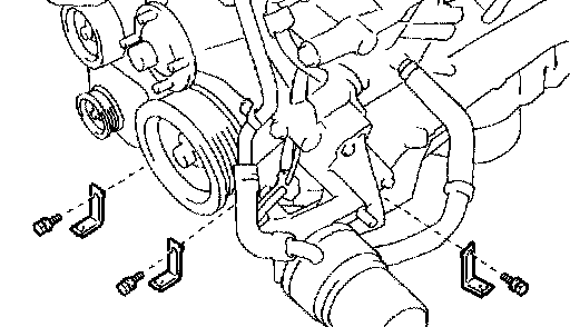
76. INSTALL HARNESS BRACKET
Torque: 8.0 Nm (80 kgf-cm, 71 inch lbs.)
77. INSTALL HEATER HOSE
78. INSTALL ENGINE MOUNTING BRACKET FRONT No.1 LH
a. Install the engine mounting bracket and engine mounting insulator with 4 bolts
Torque: 36 Nm (367 kgf-cm, 27 ft. lbs.)
79. INSTALL ENGINE MOUNTING BRACKET FRONT No.1 RH
a. Install the engine mounting bracket and engine mounting insulator with 4 bolts
Torque: 36 Nm (367 kgf-cm, 27 ft. lbs.)
80. INSTALL ENGINE WIRE No.2
a. Install engine wire protector with 3 bolts
b. Connect the ground cable wire clamp with bolt.
81. INSTALL WIRING HARNESS HEAT INSULATOR No.2
a. Install the wiring harness heat insulator with 2 bolts.
Torque: 17 Nm (175 kgf-cm, 13 ft. lbs.)
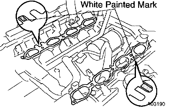
82. INSTALL INTAKE MANIFOLD ASSY
a. Place 2 new gaskets on the cylinder heads with white painted mark facing upward.
NOTICE: Align the port holes of the gasket and cylinder head. Be careful of the installation direction.
b. Place the intake manifold assembly on the cylinder heads.
c. Install and uniformly tighten the 6 bolts and 4 nuts in several passes.
Torque: 18 Nm (185 kgf-cm, 13 ft. lbs.)
83. INSTALL ENGINE WIRE
84. INSTALL ENGINE ASSY
a. Attach the engine chain hoist to the engine hangers.
b. Slowly lower the engine assembly into the engine compartment.
c. Attach the engine mounting brackets to the frame brackets.
d. Install the 4 nuts and 4 bolts holding the engine mounting brackets to the frame brackets.
Torque: 38 Nm (387 kgf-cm, 28 ft. lbs.)
e. Remove the engine chain hoist.
85. INSTALL ENGINE WIRE
86. CONNECT HEATER HOSE
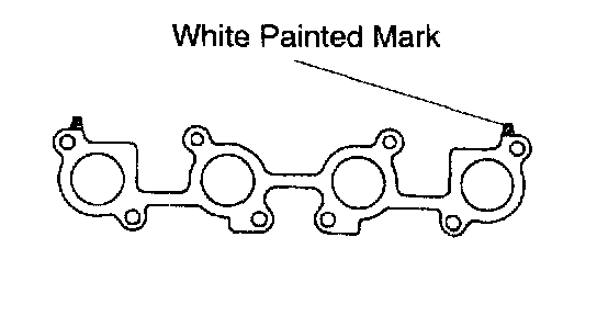
87. INSTALL EXHAUST MANIFOLD SUB-ASSY LH
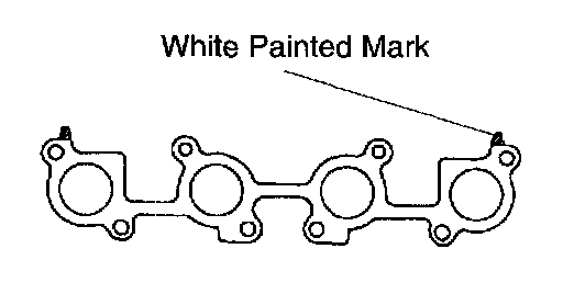
a. Place a new gasket on the cylinder head with the white painted marks facing the manifold side.
NOTICE: Be careful of the installation direction.
b. Install the exhaust manifold with 8 new nuts. Uniformly tighten the nuts in several passes.
Torque: 44 Nm (450 kgf-cm, 33 ft. lbs.)
c. Install the heat insulator with the 4 bolts.
Torque: 7.8 Nm (80 kgf-cm, 69 inch lbs.)
88. INSTALL EXHAUST MANIFOLD SUB-ASSY RH
a. Place a new gasket on the cylinder head with the white painted marks facing the manifold side.
NOTICE: Be careful of the installation direction.
b. Install the exhaust manifold with 8 new nuts. Uniformly tighten the nuts in several passes.
Torque: 44 Nm (450 kgf-cm, 33 ft. lbs.)
c. Install the heat insulator with the 4 bolts.
Torque: 7.5 Nm (76 kgf-cm, 66 inch lbs.)
89. INSTALL OIL LEVEL GAGE GUIDE
a. Install the new O-ring to the oil level gage guide.
b. Install the oil level gage guide with the belt.
Torque: 15 Nm (155 kgf-cm, 11 ft. lbs.)
90. INSTALL TRANSMISSION OIL FILLER TUBE SUB-ASSY
a. Install the transmission oil filler tube sub-assy with the bolt.
Torque: 12 Nm (122 kgf-cm, 9 ft. lbs.)
91. INSTALL FAN W/ FLUID COUPLING
a. Install the fan pulley to the engine
b. Install the fan w/ fluid coupling with the 4 nuts
Torque: 29 Nm (296 kgf-cm, 21 ft. lbs.)
92. INSTALL COMPRESSOR
a. Install the compressor with stay, nut and 3 bolts
Torque:
Bolt 47 Nm (475 kgf-cm, 34 ft. lbs.)
Nut 25 Nm (255 kgf-cm, 18 ft. lbs.)
93. INSTALL GENERATOR ASSY
94. INSTALL VANE PUMP ASSY
a. Install the vane pump assy with nut and 2 bolts
Torque:
Bolt 43 Nm (438 kgf-cm, 32 ft. lbs.)
Nut 43 Nm (438 kgf-cm, 32 ft. lbs.)
95. INSTALL FAN AND GENERATOR V BELT
96. CONNECT FUEL VAPOR FEED HOSE ASSY
97. CONNECT FUEL HOSE
98. CONNECT FUEL HOSE No.2
99. INSTALL FAN SHROUD
a. Install the fan shroud with fan into the engine room
b. Clamp the 2 oil cooler hoses to fan shroud
Torque: 5.0 Nm (51 kgf-cm, 44 inch lbs.)
100. INSTALL RADIATOR ASSY
101. REFILL ENGINE COOLANT
102. ADD ENGINE OIL
103. INSTALL ENGINE UNDER COVER ASSY REAR
104. INSTALL ENGINE UNDER COVER SUB-ASSY No.1
105. INSTALL AIR CLEANER ASSY
a. Install the air cleaner assy with 3 bolts
Torque: 12 Nm (122 kgf-cm, 9 ft. lbs.)
b. Connect the wire harness clamp and ground cable
Torque: 8.3 Nm (85 kgf-cm, 73 inch lbs.)
106. INSTALL AIR CLEANER HOSE ASSY
107. INSTALL THROTTLE BODY COVER SUB-ASSY
a. Install the throttle body cover sub-assy with 2 nuts
Torque: 7.5 Nm (80 kgf-cm, 66 inch lbs.)
108. INSTALL HOOD SUB-ASSY
a. Install the hood with 4 bolt's
Torque: 13 Nm (133 kgf-cm, 10 ft. lbs.)
b. Connect the windshield washer hose
109. INSTALL AUTOMATIC TRANSMISSION ASSY (4WD DRIVE TYPE)
110. INSTALL AUTOMATIC TRANSMISSION ASSY (2WD DRIVE TYPE)
111. CHECK FOR ENGINE COOLANT LEAKS
112. CHECK FOR EXHAUST GAS LEAKS
113. INSPECT FOR FUEL LEAKS
114. INSPECT AUTOMATIC TRANSMISSION FLUID
115. INSPECT ENGINE OIL LEAKS