Removal
Part 1 Of 6:

Part 2 Of 6:

Part 3 Of 6:

Part 4 Of 6:

Part 5 Of 6:

Part 6 Of 6:
REMOVAL
1. REMOVE BATTERY
2. REMOVE ECU BOX
3. DRAIN ENGINE COOLANT
4. DISCONNECT ENGINE COOLANT RESERVOIR
5. REMOVE AIR CLEANER ASSEMBLY
6. DISCONNECT ACCELERATOR CABLE
7. REMOVE DRIVE BED AND ALTERNATOR
8. REMOVE EXHAUST PIPE
9. 1ZZ-FE: REMOVE EXHAUST MANIFOLD
a. Remove the 3 bolts and exhaust manifold stay.
b. Remove the 6 bolts and upper heat insulator.

c. Remove the 5 nuts, exhaust manifold and gasket.
d. Remove the 3 bolts and lower heat insulator.
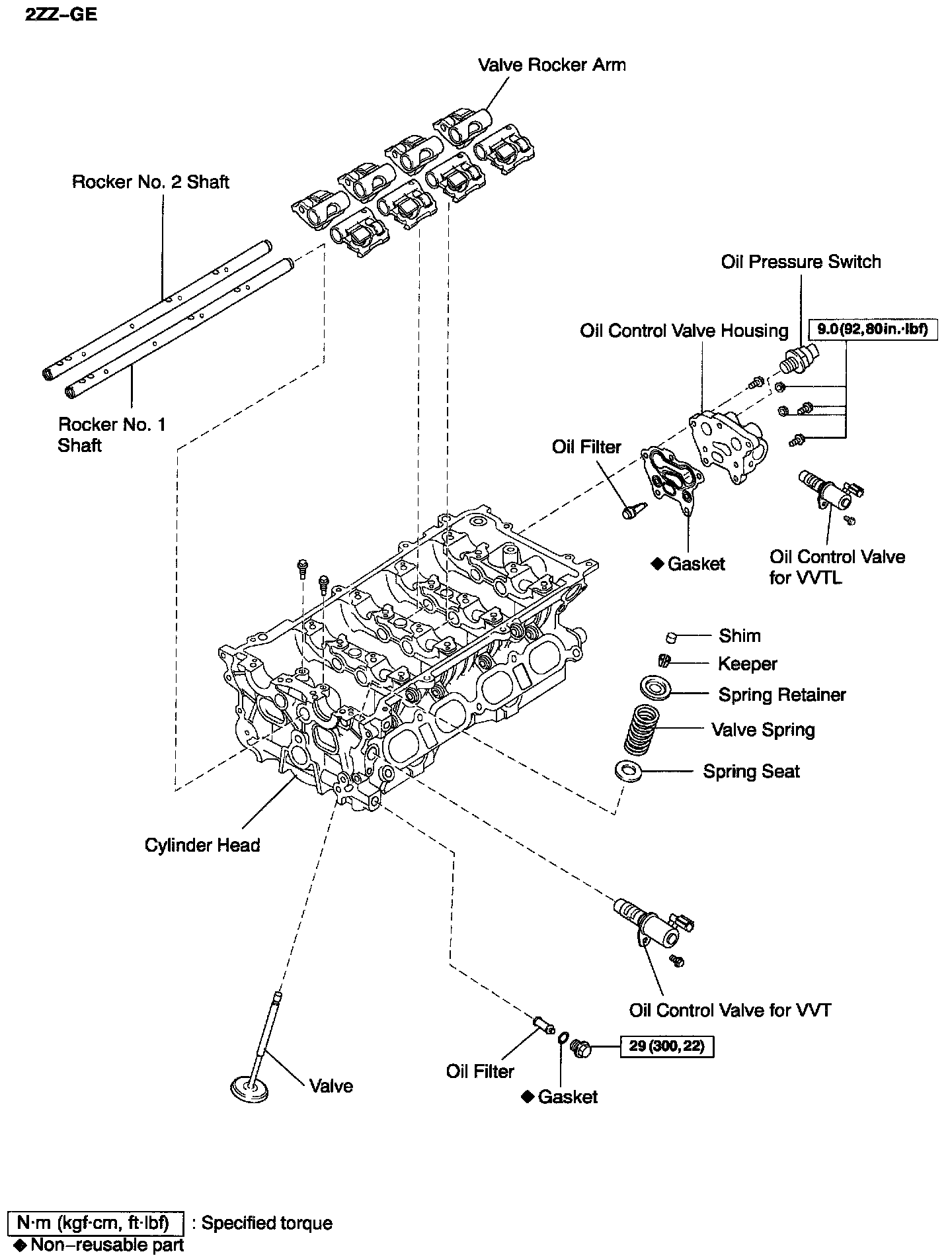
10. 2ZZ-GE: REMOVE EXHAUST MANIFOLD
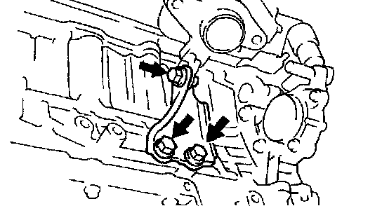
a. Remove the 4 bolts and exhaust manifold stay.
b. Remove the 5 bolts and upper heat insulator.

c. Remove the 3 bolts, 2 nuts, exhaust manifold and gasket.
d. Remove the 4 bolts and lower heat insulator.
11. REMOVE IGNITION COIL
12. REMOVE SPARK PLUG
13. REMOVE PCV HOSES
14. REMOVE THROTTLE BODY
15. REMOVE INJECTOR
Remove the 3 bolts, 2 nuts, exhaust manifold and gasket.
16. 1ZZ-FE: DISCONNECT ENGINE WIRE FROM CYLINDER HEAD
a. Disconnect the ECT sensor connector.
b. Disconnect the camshaft position sensor connector.
c. Disconnect the oil control valve for VVT connector.
d. Disconnect the 2 ground wires.
e. Disconnect the 2 clamps and engine wire protector from the intake manifold.

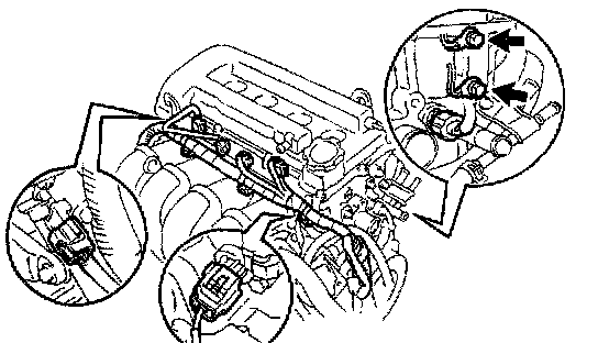
17. 2ZZ-GE: DISCONNECT ENGINE WIRE FROM CYLINDER HEAD
a. Disconnect the ECT sensor connector.
b. Disconnect the camshaft position sensor connector.
c. Disconnect the oil control valve for VVT connectors.
d. Disconnect the oil control valve for VVTL connectors.
e. Disconnect the oil pressure switch connector.
f. Disconnect the 2 ground wires.
g. Remove the 2 bolts, and disconnect the engine wire.
h. Remove the intake manifold No. 2 insulator.

18. 1ZZ-FE: REMOVE INTAKE MANIFOLD
a. Disconnect the EVAP hose for ORVR.
b. Disconnect the brake booster vacuum hose.
c. Remove the 4 bolts, 2 nuts, intake manifold, 2 wire harness stays and gasket.

19. 2ZZ-GE: REMOVE INTAKE MANIFOLD
a. Disconnect the EVAP hose for ORVR.
b. Disconnect the brake booster vacuum hose.
c. Remove the bolt and disconnect the No. 1 ventilation pipe and oil dipstick and guide.
d. Remove the 2 bolts, nut and stay.
e. Remove the 4 bolts, 2 nuts, intake manifold and gasket.
f. Remove the intake manifold insulator.
20. REMOVE CAMSHAFT POSITION SENSOR
21. REMOVE ECT SENSOR
22. REMOVE PCV VALVE AND GROMMET
23. REMOVE OIL FILLER CAP
24. REMOVE CAMSHAFT TIMING SPROCKETS

25. 1ZZ-FE: REMOVE CAMSHAFT
Unit firmly loosen and remove the 19 bearing cap bolts, in several passes, in the sequence shown, and remove the 9 bearing cape;, intake and exhaust camshafts.
26. 2ZZ-GE: REMOVE CAMSHAFT
Uniformly loosen and remove the 20 bearing cap bolts, in several passes, in the sequence shown, and remove the 9 bearing cape intake and exhaust camshaft.
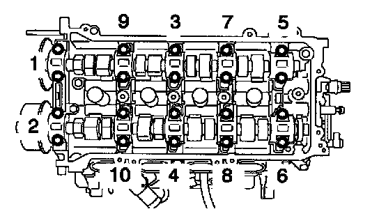
27. REMOVE CYLINDER HEAD
a. Disconnect the upper radiator hoses from the water hose union.
b. Disconnect the heater water hose from the water hose union.

c. Using a 10 mm bi-hexagon wrench, uniformly loosen and remove the 10 cylinder head bolts, in several passes, in the sequence shown. Remove the 10 cylinder head bolts and plate washers.
NOTICE: Head warpage or cracking could result from removing bolts in an incorrect order.
d. Remove the bolt holding the water bypass pipe to the cylinder head.

e. Lift the cylinder from the dowels on the cylinder block and replace the cylinder head on wooden blocks on a bench.
HINT: If the cylinder head is difficult to lift off, pry between the cylinder head and cylinder block with a screwdriver.
NOTICE: Be careful not to damage the contact surfaces of the cylinder head and cylinder block.