Engine Removal
Part 1 Of 4:
Part 2 Of 4:
Part 3 Of 4:
Part 4 Of 4:

REMOVAL
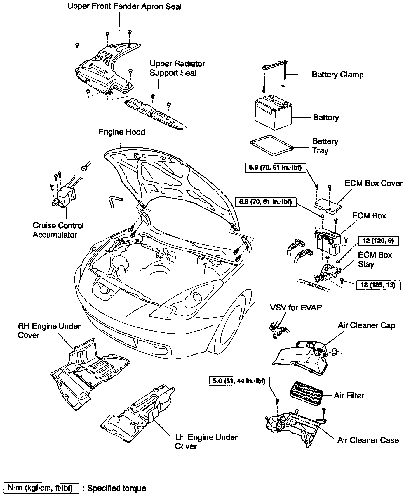
1. REMOVE BATTERY AND TRAY
2. REMOVE HOOD
3. REMOVE ENGINE UNDER COVERS
4. DRAIN ENGINE COOLANT
5. DRAIN ENGINE OIL
6. DRAIN TRANSAXLE OIL
7. REMOVE BUMPER COVER AND HEAD LIGHT

8. REMOVE AIR CLEANER CAP
a. Disconnect the MAP meter connector.
b. Disconnect the VSV for EVAP.
c. Disconnect the 2 hoses.
d. Disconnect the 3 clamps, and disconnect the air cleaner cap from the air cleaner case.
e. Loosen the hose clamp, and disconnect the air cleaner hose from the throttle body.

9. REMOVE AIR CLEANER CASE
a. Remove the air filter.
b. Disconnect the hose from the VSV for Canister Closed VALVE (CVC).
c. Disconnect the hose from the intake air control valve.
d. Remove the 2 bolts, and disconnect the air cleaner case.
e. Disconnect the 2 hoses from the air cleaner case.
10. REMOVE ECM BOX
a. Remove the 2 bolts and ECM cover.
b. Disconnect the 4 connectors from the ECM.
c. Disconnect the 2 connectors from the ECM box.
d. Remove the ECM from the ECM box.
e. Disconnect the clamp from the ECM box.
f. Disconnect the 2 engine wires from the ECM box.
g. Remove the 3 bolts and ECM box.

h. Remove the 2 nuts, bolt and ECM box stay.
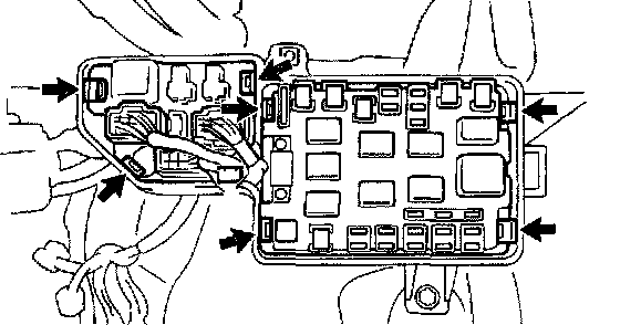
11. DISCONNECT ENGINE WIRE FROM ENGINE COMPARTMENT RELAY BOX
a. Remove the relay box upper cover.
b. Disconnect the 3 connectors.
c. Disconnect the 7 claws and J/B from the relay box.

d. Disconnect the 3 connectors.
e. Disconnect the engine wire from the relay box.
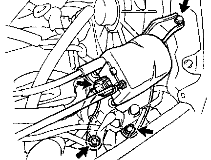
12. w/ Cruise Control System: DISCONNECT CRUISE CONTROL ACTUATOR
a. Disconnect the actuator connector.
b. Remove the 3 bolts and disconnect the actuator from the body.
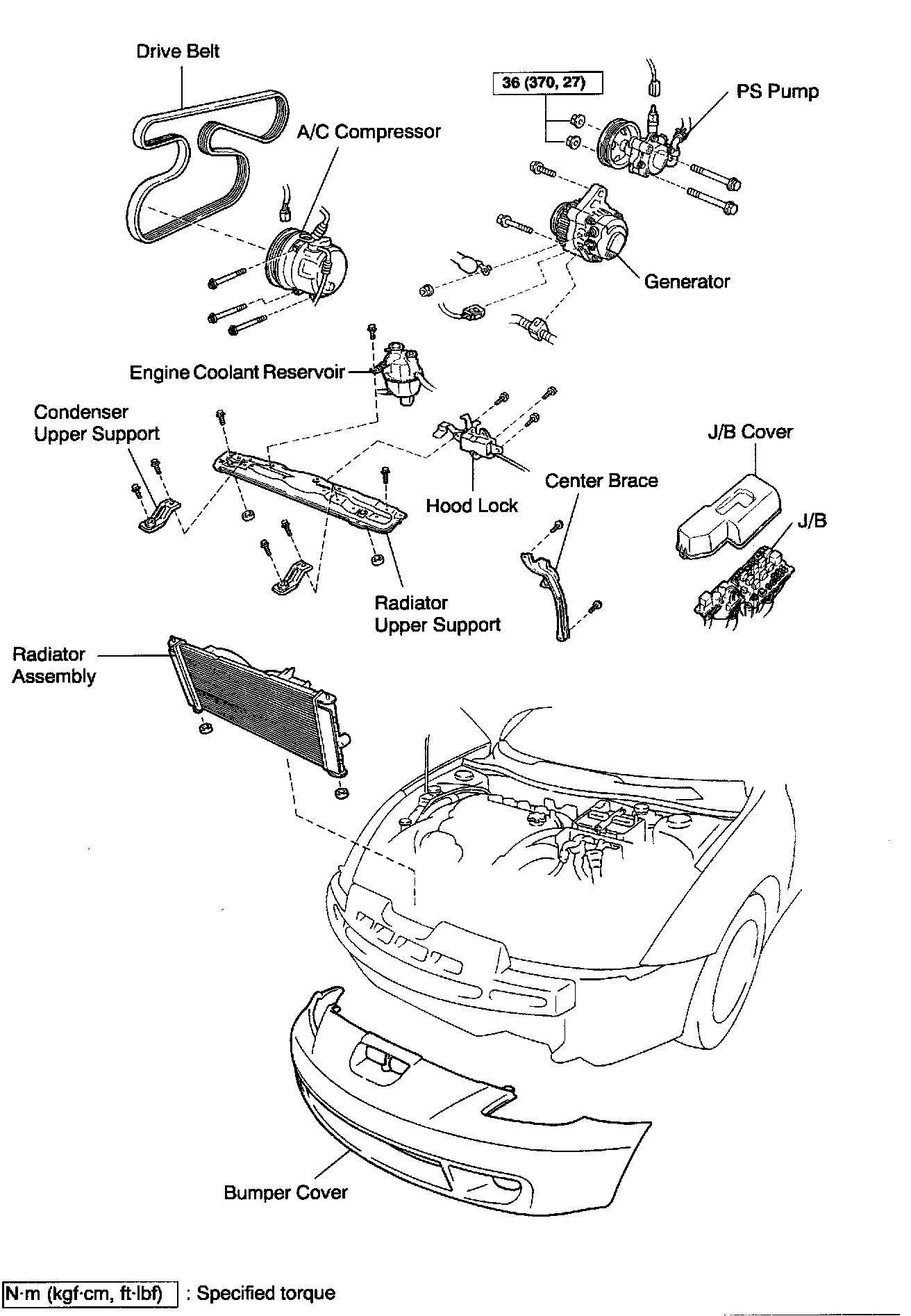
13. REMOVE RADIATOR ASSEMBLY
14. REMOVE DRIVE BED AND GENERATOR

15. w/A/C: DISCONNECT A/C COMPRESSOR
a. Disconnect the A/C compressor connector.
b. Remove the 3 bolts, and disconnect the ARC compressor from the engine.
HINT: Suspend the A/C compressor securely
16. DISCONNECT TUBE AND HOSE
a. Disconnect the fuel tube from the fuel pipe on vehicle side.
b. Disconnect the 2 heater hoses from the engine side.
c. Disconnect the brake booster vacuum hose.

17. M/T: DISCONNECT CLUTCH RELEASE CYLINDER
Remove the 3 bolts, and disconnect the brackets from the transaxle.
b. Remove the 2 bolts, and disconnect the release cylinder from the transaxle.
18. DISCONNECT TRANSAXLE CONTROL CABLE (S)
19. DISCONNECT 2 GROUND CABLES
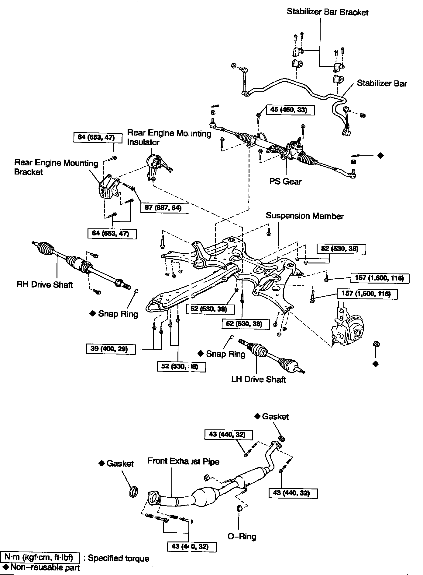
20. REMOVE DRIVE SHAFT
21. REMOVE EXHAUST PIPE

a. Disconnect the 2 heated oxygen sensor.

b. Remove the 4 bolts and springs.
c. Disconnect the 2 O-rings, and remove the exhaust pipe and 2 gaskets.

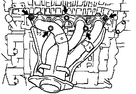
22. 1ZZ-FE: REMOVE EXHAUST MANIFOLD
a. Remove the 6 bolts and upper heat insulator.
b. Remove the 3 bolts and exhaust manifold stay.
c. Remove the 5 nuts, exhaust manifold and gasket.
23. 2ZZ-GE: REMOVE EXHAUST MANIFOLD
a. Remove the 5 bolts and upper heat insulator.
b. Remove the 4 bolts and exhaust manifold stay.
c. Remove the 2 nuts, 3 bolts, exhaust manifold and gasket.
24. DISCONNECT PS PUMP
a. Disconnect the PS oil pressure switch connector.
b. Remove the 2 nuts and through bolts, and disconnect the PS pump from the engine.
HINT: Put aside the pump and suspend it to the cowl with a string.
25. REMOVE STABILIZER BAR BRACKET
26. DISCONNECT PS GEAR
Remove the 4 bolts, and disconnect the PS gear from the suspension member.
HINT: Suspend the PS gear securely.

27. REMOVE SUSPENSION MEMBER
Remove the 9 bolts, 3 nuts and suspension member.
28. ATTACH ENGINE SLIDING DEVICE TO ENGINE HANGER
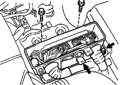
a. Remove the 4 bolts and No. 2 cylinder head cover.
b. Disconnect the PCV hoses from the cylinder head cover.

c. Install the 2 engine hangers in the correct direction.
Engine hanger part No.:
1ZZ-FE
Front: 12281-22021
Rear: 12281-15040 or 12281-15050
Bolt: 91512-B1016
2ZZ-GE
Front: 12281-88600
Rear: 12282-88600
Bolt: 91512-61020
Torque: 38 Nm (388 kgf-cm, 28 ft. lbs.)
d. Attach the engine sling device to the engine hangers.
CAUTION: Do not attempt to hang the engine by hooking the chain to any other part.
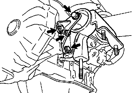
29. REMOVE REAR ENGINE MOUNTING
a. Remove the through bolt and rear engine mounting insulator.
b. Remove the 3 bolts and rear engine mounting bracket.

30. REMOVE ENGINE AND TRANSAXLE ASSEMBLY
a. Remove the LH engine mounting through bolt and nut.

b. 1ZZ-FE: Remove the 4 bolts, 2 nuts and RH engine mounting insulator.
c. 2ZZ-GE: Remove the 5 bolts, 2 nuts and RH engine mounting insulator.

d. Lower the engine out of vehicle slowly and carefully, and raise the vehicle.
HINT: Make sure the engine is clear of all wiring, hoses and cables.
e. Place the engine and transaxle assembly onto the stand.
31. SEPARATE ENGINE AND TRANSAXLE