Component Tests and General Diagnostics
INSPECTION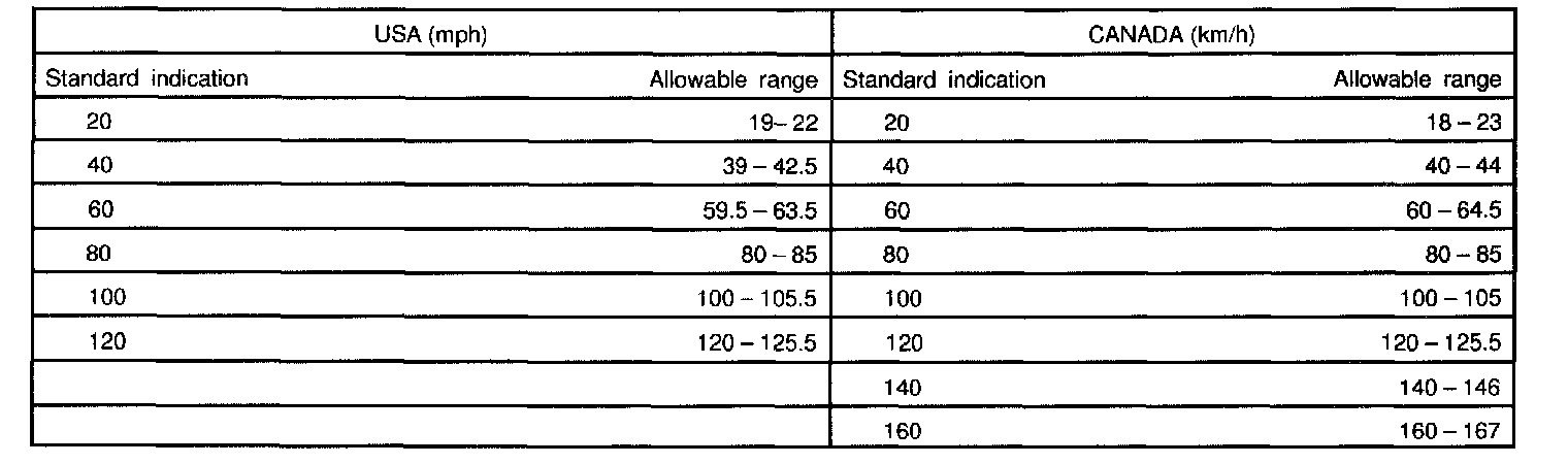
1. INSPECT SPEEDOMETER ON-VEHICLE
Using a speedometer tester, inspect the speedometer for allowable indication error and check the operation of the odometer.
HINT: Tire wear and tire over or under inflation will increase the indication error.
If error is excessive replace the speedometer.


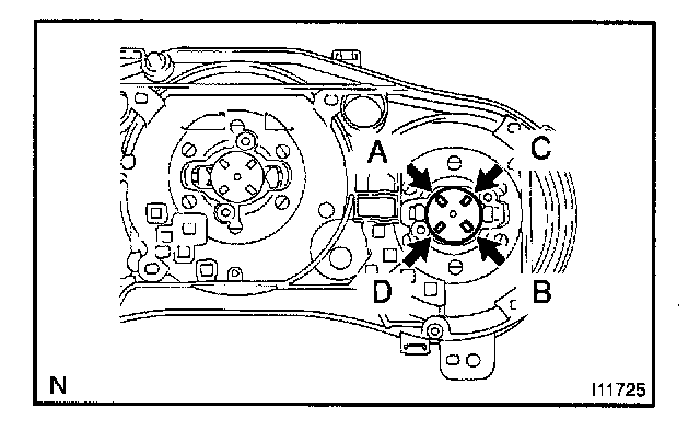
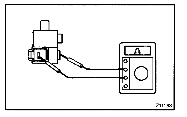
2. INSPECT SPEEDOMETER RESISTANCE
Measure the resistance between terminals with fixing pointer to the stopper.
If resistance value is not as specified, replace the meter.

3. INSPECT VEHICLE SPEED SENSOR OPERATION
a. Connect the positive (+) lead from battery to terminal 1 and negative (-) lead to terminal 2.
b. Connect the positive (+) lead from tester to terminal 3 and negative (-) lead to terminal 2.
c. Rotate shaft.
d. Check that there is voltage change from approx. 0 V to 11 V or more between terminals 2 and 3.
HINT: The voltage change should be 4 times for every revolution of the speed sensor shaft.
If operation is not as specified, replace the sensor.
4. INSPECT TACHOMETER ON-VEHICLE
a. Connect a tune-up test tachometer, and start the engine.
NOTE: Reversing the connection of the tachometer will damage the transistors and diodes inside.
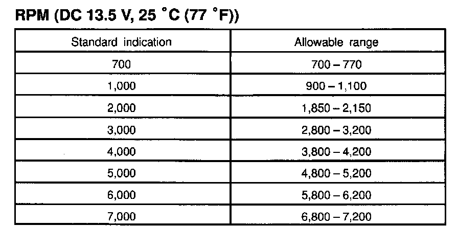
b. Compare the tester indications with tachometer indications.
If error is excessive, replace the tachometer.

5. INSPECT TACHOMETER RESISTANCE
Measure the resistance between terminals with fixing pointer to the stopper.
If resistance value is not as specified, replace the meter.
6. INSPECT FUEL RECEIVER GAUGE OPERATION

a. Disconnect the connector from the sender gauge assembly.
b. Turn the ignition switch ON, check that the receiver gauge needle indicates EMPTY

c. Connect terminals 2 and 3 of the wire harness side connector through a 3.4 W test bulb.
d. Turn the ignition switch ON, check that the bulb lights up and receiver gauge needle indicators EMPTY
If operation is not as specified, inspect the sender gauge resistance.


7. INSPECT FUEL SENDER GAUGE RESISTANCE
Measure the resistance between terminals 2 and 3 for each float position.
If resistance value is not as specified, replace the sender gauge.
If resistance value is as specified, replace the combination meter.
8. INSPECT ENGINE COOLANT TEMPERATURE RECEIVER GAUGE OPERATION

a. Disconnect the connector from the sender gauge.
b. Turn the ignition switch ON, check that the receiver gauge needle indicates COOL.

c. Ground terminal of the wire harness side connector through a 3.4 W test bulb.
d. Turn the ignition switch ON, check that the bulb lights up and the receiver gauge needle moves toward the hot side.
If operation is not as specified, inspect the sender gauge. Then recheck the system.
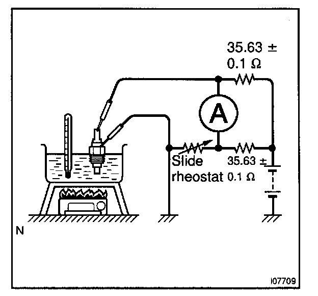
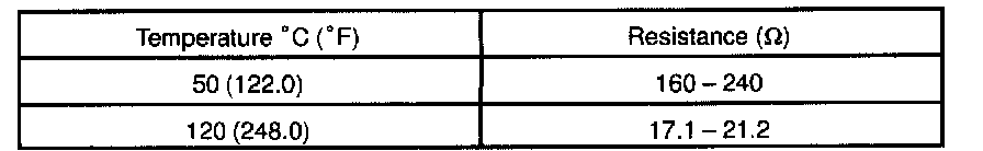
9. INSPECT ENGINE COOLANT TEMPERATURE SENDER GAUGE RESISTANCE
Connect the wire harness as shown in the illustration, and adjust the ammeter pointer to indicate "0" using the slide rheostat, then read the rheostat indication.
If resistance value is not as specified, replace the engine coolant temperature sender gauge.
If resistance value is as specified, replace the combination meter.

10. INSPECT LOW OIL PRESSURE WARNING LIGHT
a. Disconnect the connector from the warning switch and ground terminal of the wire harness side connector.
b. Turn the ignition switch ON, check that the warning light lights up.
If the warning light does not light up, test the bulb or inspect wire harness.

11. INSPECT LOW OIL PRESSURE SWITCH CONTINUITY
a. Check that continuity exists between terminal and ground with the engine stopped.
b. Check that no continuity exists between terminal and ground with the engine running.
HINT: Oil pressure should be over 24.5 kPa (0.25 kgf/sq.cm, 3.55 psi).
If operation is not as specified, replace the switch.

12. INSPECT BRAKE WARNING SYSTEM LIGHT
a. Disconnect the connector from the brake fluid warning switch.
b. Connect terminals of the wire harness side of the level warning switch connector.
c. Start the engine, check that the warning light lights up. If the warning light does not light up, test the bulb or wire harness.

13. INSPECT BRAKE FLUID LEVEL WARNING SWITCH CONTINUITY
a. Remove the reservoir tank cap and strainer.
b. Disconnect the connector.
c. Check that no continuity exists between terminals with the switch OFF (float up).
d. Use syphon, etc. to take fluid out of the reservoir tank.
e. Check that continuity exists between terminals with the switch ON (float down).
f. Pour the fluid back in the reservoir tank.
If operation is not as specified, replace the switch.

14. INSPECT PARKING BRAKE WARNING LIGHT
a. Disconnect the connector from the parking brake switch.
b. Ground terminal of the wire harness side connector.
c. Start the engine, check that the warning light lights up.
If the warning light does not light up, test the bulb or inspect wire harness.
15. INSPECT PARKING BRAKE SWITCH CONTINUITY
a. Check that continuity exists between terminal and switch body with the switch ON (switch pin released).
b. Check that no continuity exists between terminal and switch body with the switch OFF (switch pin pushed in).
If operation is not as specified, replace the switch or inspect ground point.

16. INSPECT OPEN DOOR WARNING LIGHT
Disconnect the connector from the door courtesy switch, and ground terminal 1 of the wire harness side connector and check that the warning light lights up.
If the warning light does not light up, inspect the bulb or wire harness.
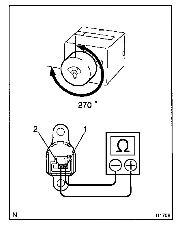
17. INSPECT LIGHT CONTROL RHEOSTAT OPERATION
Gradually, turn the rheostat knob from the bright side to dark side and check that the resistance decreases from 10 kohm to 0 ohm between terminal 2 and 1. (Rheostat knob turned to clockwise)
If operation is not as specified, replace the rheostat light control.