Disassembly and Assembly
DISASSEMBLY
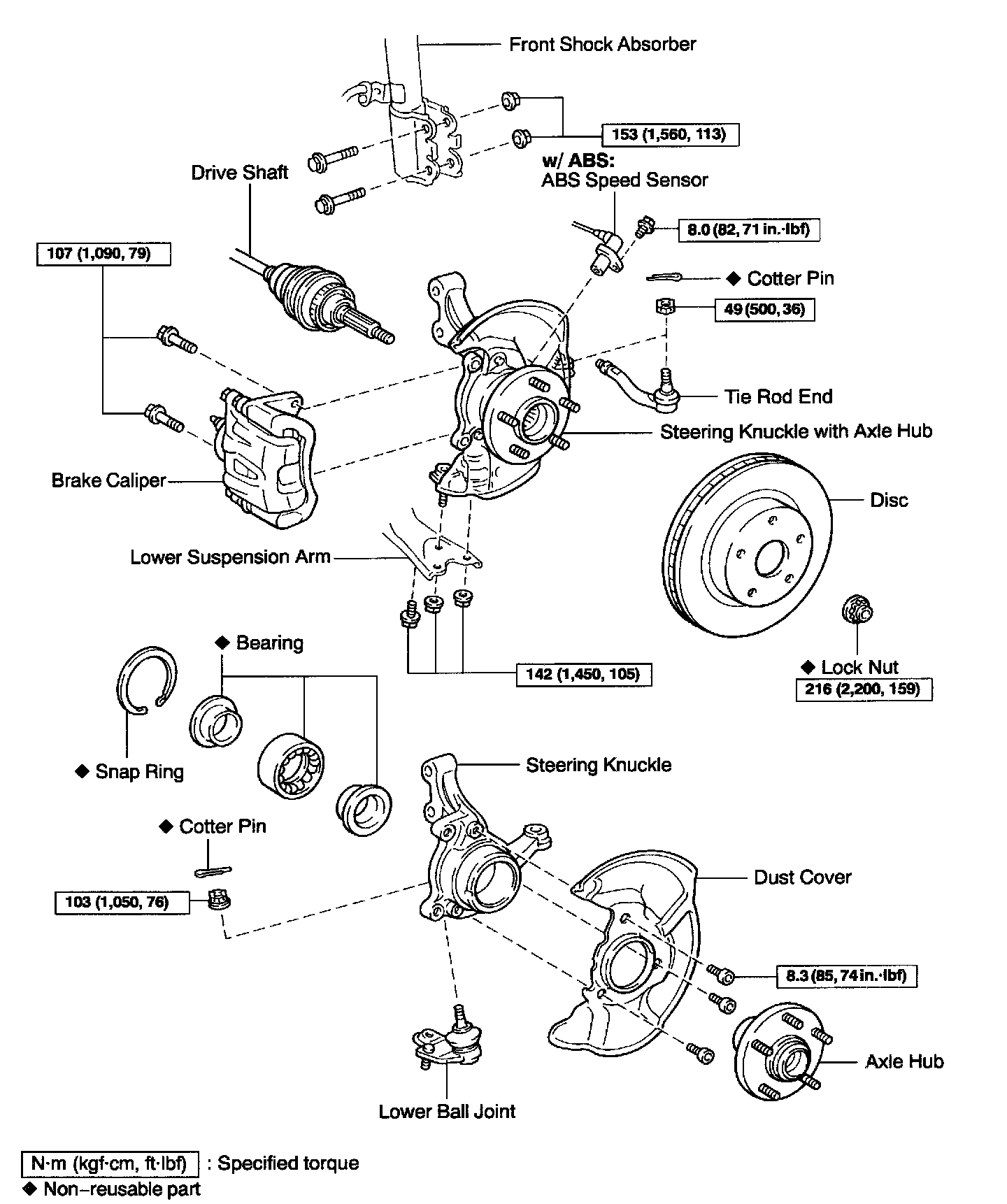
1. REMOVE LOWER BALL JOINT
a. Remove the cotter pin and nut.

b. Using SST, remove the lower ball joint.
SST 09628-62011
2. REMOVE AXLE HUB

a. Using SST, remove the axle hub.
SST 09520-00031 (09520-00040, 09521-00010, 09521-00020)

b. Using SST and a press, remove the inner race (outside) from the axle hub.
SST 09555-55010, 09950-60010 (09951-00380), 09950-70010 (09951-07150)
3. REMOVE DUST COVER
Using a torx socket (T30), remove the 3 bolts and dust cover.
4. REMOVE BEARING FROM STEERING KNUCKLE
a. Using snap ring pliers, remove the snap ring.
b. Place the inner race on the outside of the bearing.

c. Using SST and a press, remove the bearing.
SST 09527-17011, 09950-60010 (09951-00650), 09950-70010 (09951-07150)
REASSEMBLY
1. INSTALL BEARING

a. Using SST and a press, install a new bearing to the steering knuckle.
SST 09950-60020 (09951-00730), 09950-70010 (09951-07150)
b. Using snap ring pliers, install a new snap ring.
2. INSTALL DUST COVER
Place the dust cover and using a torx socket (T30), install the 3 bolts.
Torque: 8.3 Nm (85 kgf-cm, 74 inch lbs.)

3. INSTALL FRONT AXLE HUB
Using SST and a press, install the axle hub.
SST 09608-32010, 09950-60010 (09951-00550) 09950-70010 (09951-07150)
4. INSTALL LOWER BALL JOINT
a. Install the lower ball joint and tighten the nut.
Torque: 103 Nm (1,050 kgf-cm, 76 ft. lbs.)
b. Install a new cotter pin.
If the holes for the cotter pin are not aligned, tighten the nut further up to 60°.