Fuel Pump Control Circuit
CIRCUIT DESCRIPTION
In the diagram, when the engine is cranked, current flows from terminal ST of the ignition switch to the starter relay coil and also current flows to terminal STA of ECM (STA signal).
When the STA signal and NE signal are input to the ECM, Tr is turned ON, current flows to coil of the circuit opening relay, the relay switches on, power is supplied to the fuel pump and the fuel pump operates. While the NE signal is generated (engine running), the ECM keeps Tr ON (circuit opening relay ON) and the fuel pump also keeps operating.
Wiring Diagram:

INSPECTION PROCEDURE
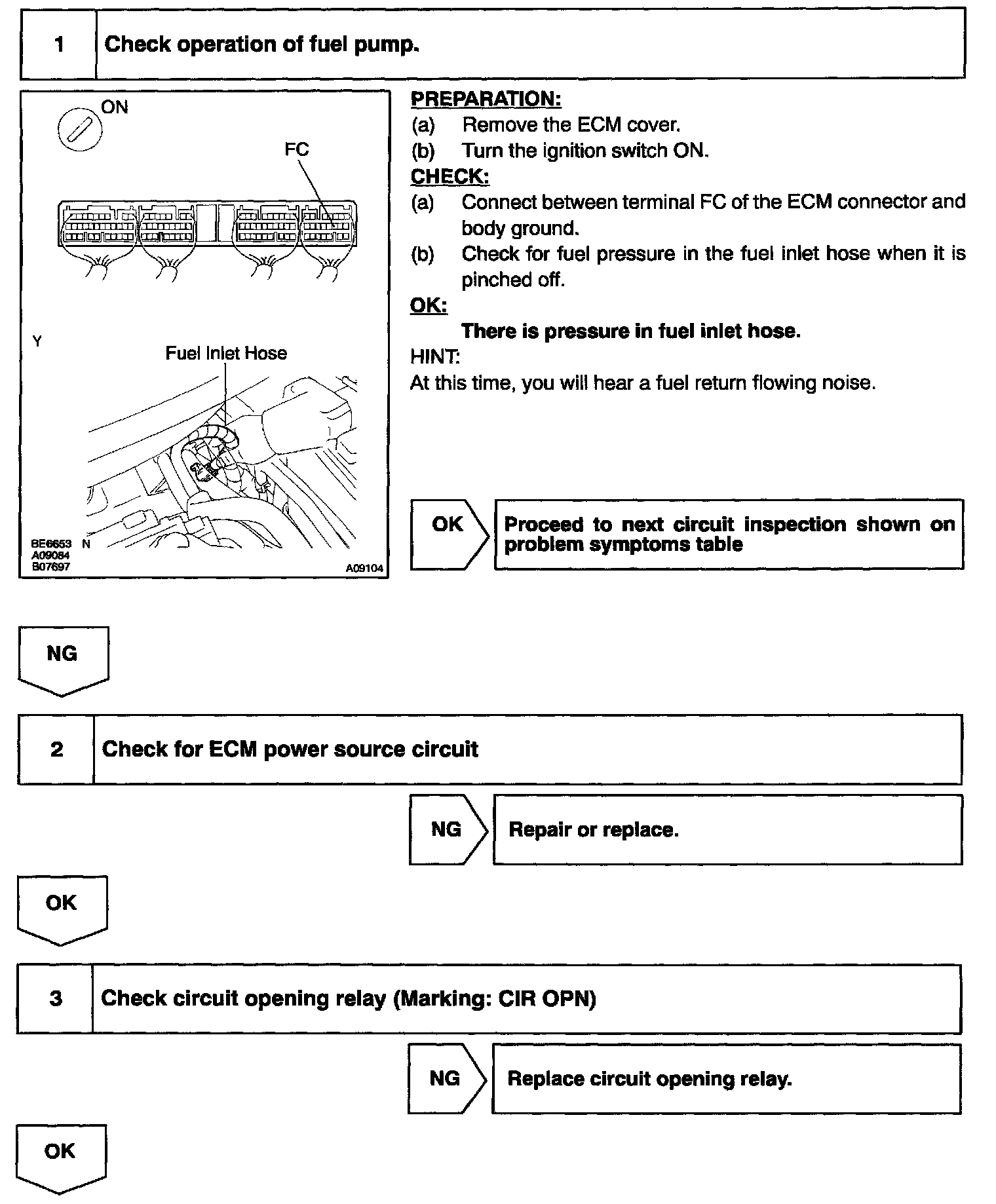
Step 1 - 3:

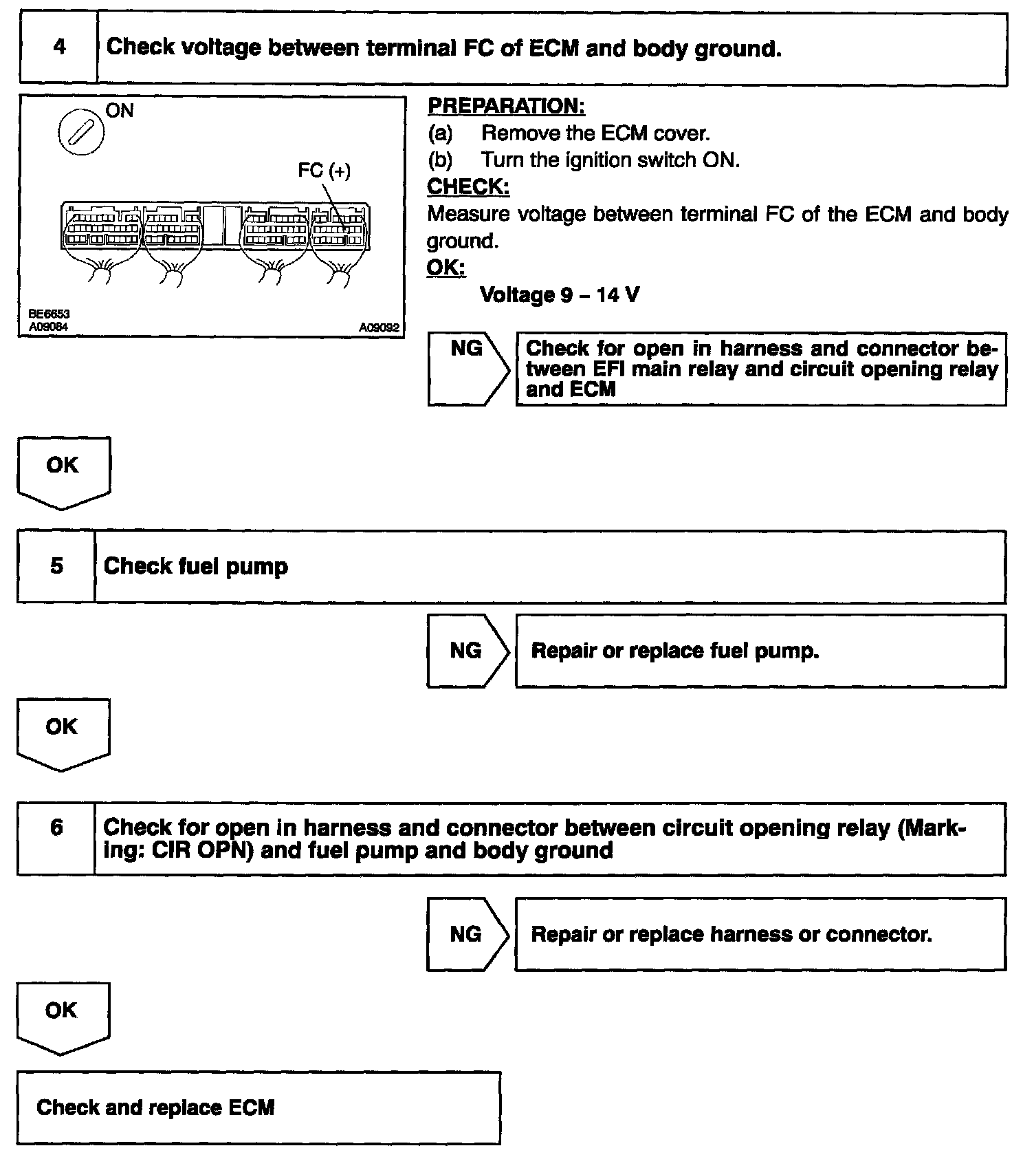
Step 4 - 6:

Hand-held tester:
Step 1 - 3:
Step 4 - 6:
OBD II scan tool (excluding hand-held tester):