Removal and Installation
REMOVAL
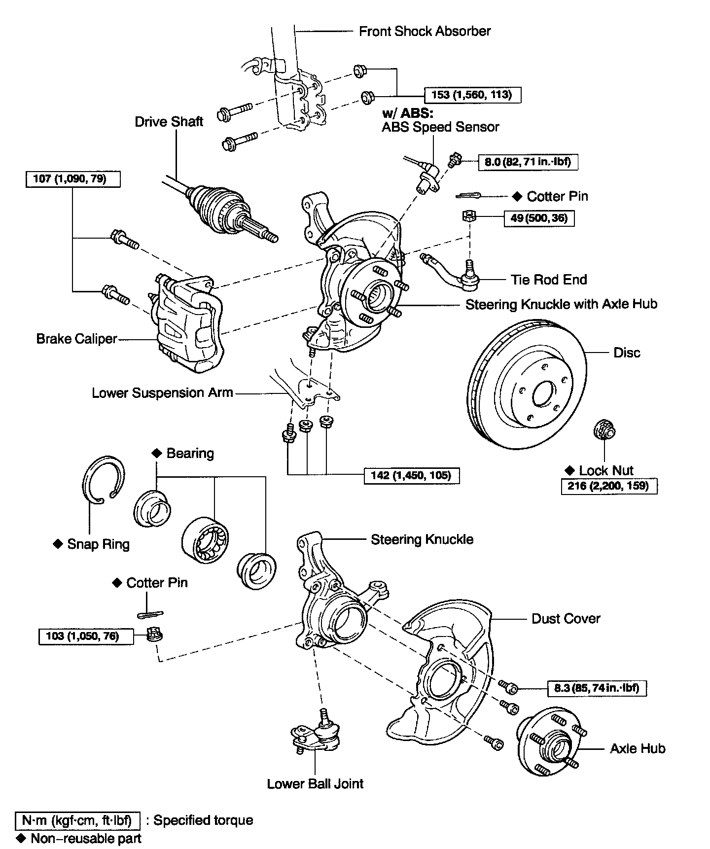
1. REMOVE FRONT WHEEL
Torque: 103 Nm (1,050 kgf-cm, 76 ft. lbs.)
2. CHECK BEARING BACKLASH AND AXLE HUB DEVIATION

a. Remove the 2 bolts, brake caliper and disc.
b. Support the brake caliper securely.

c. Using a dial indicator, check the backlash near the center of the axle hub.
Maximum: 0.05 mm (0.0020 inch)
If the backlash exceeds the maximum, replace the bearing.
d. Using a dial indicator, check the deviation at the surface of the axle hub outside the hub bolt.
Maximum: 0.07 mm (0.0028 inch)
If the deviation exceeds the maximum, replace the axle hub.
e. Install the disc, 2 bolts and brake caliper.
Torque: 107 Nm (1,090 kgf-cm, 79 ft. lbs.)
3. REMOVE DRIVE SHAFT LOCK NUT

a. Using SST and a hammer, unstake the staked part of the lock nut.
SST 09930-00010
b. While applying the brakes, remove the nut.
Torque: 216 Nm (2,200 kgf-cm, 159 ft. lbs.)
c. Remove the brake caliper and disc.
d. Support the brake caliper securely.
4. w/ ABS: REMOVE ABS SPEED SENSOR
Torque: 8.0 Nm (82 kgf-cm, 71 inch lbs.)

5. LOOSEN 2 NUTS ON LOWER SIDE OF SHOCK ABSORBER
Torque: 153 Nm (1,560 kgf-cm, 113 ft. lbs.)
HINT: Do not remove the 2 bolts and nuts.
6. DISCONNECT TIE ROD END FROM STEERING KNUCKLE
a. Remove the cotter pin and nut.
Torque: 49 Nm (500 kgf-cm, 36 ft. lbs.)
HINT: At the time of installation, if the holes for a new cotter pin are not aligned, tighten the nut further up to 60°.

b. Using SST, disconnect the tie rod end from the steering knuckle.
SST 09610-20012

7. DISCONNECT LOWER SUSPENSION ARM FROM LOWER BALL JOINT
Remove the 2 nuts and bolt.
Torque: 142 Nm (1,450 kgf-cm, 105 ft. lbs.)
8. REMOVE STEERING KNUCKLE WITH AXLE HUB
a. Remove the 2 bolts and nuts on the lower side of the shock absorber.
HINT: At the time of installation, coat the nut's thread with engine oil. Remove the steering knuckle with the axle hub.
NOTICE: Be careful not to damage the boot and ABS speed sensor rotor.
INSTALLATION
Installation is in the reverse order of removal.
HINT: After installation, check the ABS speed sensor signal and front wheel alignment.