Disassembly
Part 1 Of 3:

Part 2 Of 3:

Part 3 Of 3:

DISASSEMBLY
1. REMOVE FILLER PLUG AND DRAIN PLUG WITH 2 GASKETS
Torque: 39 Nm (400 kgf-cm, 29 ft. lbs.)
2. REMOVE VEHICLE SPEED SENSOR
Remove the bolt and vehicle speed sensor.
Torque: 11 Nm (115 kgf-cm, 8 ft. lbs.)
b. Using a small screwdriver, remove the clip from the vehicle speed sensor.
c. Remove the vehicle speed sensor driven gear from the speed sensor.
d. Using a small screwdriver, remove the O-ring from the vehicle speed sensor.
3. REMOVE BACK-UP LIGHT SWITCH WITH GASKET
Torque: 40 Nm (410 kgf-cm, 30 ft. lbs.)
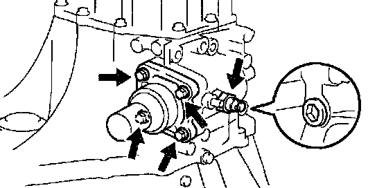
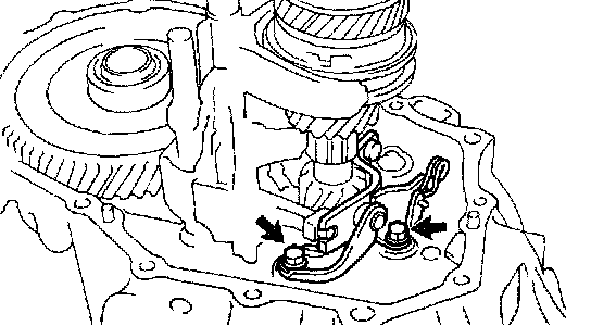
4. REMOVE CONTROL CABLE BRACKET
Remove the 2 bolts and control cable bracket.
Torque: 25 Nm (250 kgf-cm, 18 ft. lbs.)

5. REMOVE CONTROL SHAFT ASSEMBLY
Remove the 2 nuts, wave washer and control shaft assembly.
Torque: 12 Nm (120 kgf-cm, 9 ft. lbs.)
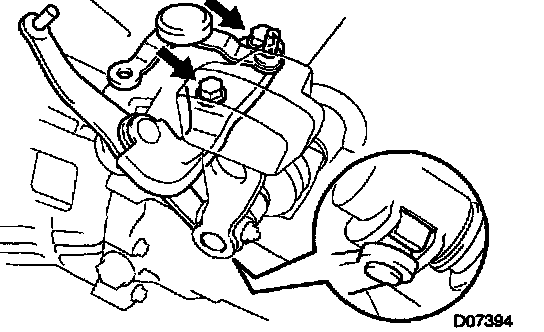
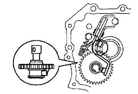
6. REMOVE SELECTING BELLCRANK ASSEMBLY
a. Remove the 2 bolts and selecting bellcrank assembly.
Torque: 25 Nm (250 kgf-cm, 18 ft. lbs.)
NOTICE:
At the time of reassembly, please refer to the following item.
Fit the selecting bellcrank assembly pin part with the dust cover into a groove in the control shift lever.
b. Remove the control bellcrank dust cover from the selecting bellcrank assembly.
NOTICE:
At the time of reassembly, please refer to the following item.
Apply MP grease to the inside circumferential surface of the control bellcrank dust cover.
7. REMOVE CONTROL SHIFT LEVER AND DUST BOOT

a. Remove the nut and wave washer.
Torque: 12 Nm (120 kgf-cm, 9 ft. lbs.)

b. Using a pin punch and hammer, drive out the lever lock pin.
NOTICE: At the time of reassembly, please refer to the following item.
When fixing the lever lock pin, properly position the shaft groove.
c. Remove the control shift lever and dust boot.
NOTICE: At the time of reassembly, please refer to the following items.
^ Install the dust boot into a groove in the control shift lever.
^ Be sure to install the dust boot in the correct direction, as shown in the illustration.
8. REMOVE PLUG, LOCK BALL ASSEMBLY AND CONTROL SHAFT COVER ASSEMBLY
a. Using a hexagon wrench, remove the plug and gasket.
Torque: 39 Nm (400 kgf-cm, 29 ft. lbs.)
b. Remove the lock ball assembly.
Sealant: Part No. 08833-00080, THREE BOND 1344, LOCTITE 242 or equivalent
Torque: 29 Nm (300 kgf-cm, 22 ft. lbs.)
c. Remove the 4 bolts and control shaft cover assembly with the gasket.
Sealant: Part No. 08833-00080, THREE BOND 1344, LOCTITE 242 or equivalent
Torque: 20 Nm (200 kgf-cm, 14 ft. lbs.)
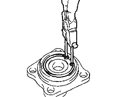
9. DISASSEMBLE CONTROL SHAFT COVER ASSEMBLY
a. Using snap ring pliers, remove the snap ring.
b. Remove the No. 3 select spring seat and compression spring.
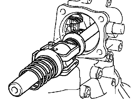
10. REMOVE SHIFT AND SELECT LEVER SHAFT ASSEMBLY
a. Remove the shift and select lever shaft assembly.
NOTICE:
At the time of reassembly, please refer to the following item.
Set the claws of the shift interlock plate into the shift head part of the gear shift fork shaft securely.
b. Remove the select spring seat and compression spring from the shift and select lever shaft assembly.
11. REMOVE TRANSMISSION CASE COVER
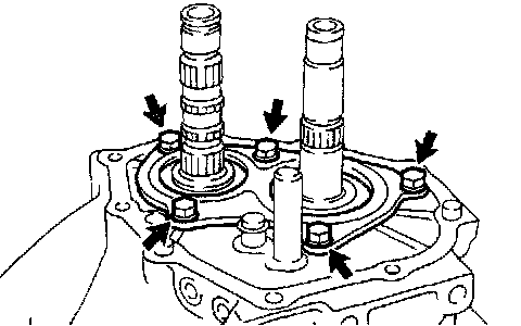
a. Remove the 9 bolts.
Torque: 18 Nm (185 kgf-cm, 13 ft. lbs.)
b. Carefully tap the projection of the transmission case cover with a brass bar and hammer and remove it.

HINT:
At the time of reassembly, please refer to the following item.
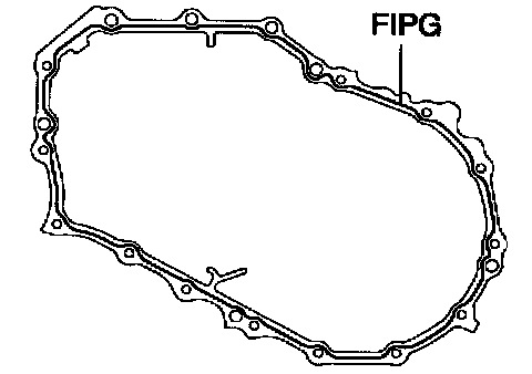
Apply FIPG to the transmission case side, as shown in the illustration.
FIPG: Part No. 08826-00090, THREE BOND 1281 or equivalent

12. INSPECT 6TH GEAR THRUST CLEARANCE
Using a dial indicator, measure the thrust clearance.
Standard clearance: 0.10 - 0.60 mm (0.0039 - 0.0236 inch)
Maximum clearance: 0.60 mm (0.0236 inch)

13. INSPECT 6TH GEAR RADIAL CLEARANCE
Using a dial indicator, measure the radial clearance.
Standard clearance: 0.009 - 0.050 mm (0.0003 - 0.0020 inch)
Maximum clearance: 0.050 mm (0.0020 inch)
If the clearance exceeds the maximum, replace the gear, needle roller bearing or shaft.

14. REMOVE OUTPUT SHAFT REAR RADIAL BALL BEARING, 6TH DRIVEN GEAR AND SPACER
a. Using 2 screwdrivers and a hammer, tap out the snap ring.

HINT:
At the time of reassembly, please refer to the following item.
Select a snap ring from the table that will make the thrust clearance of the output shaft rear radial ball bearing less than 0.1 mm (0.0039 inch).

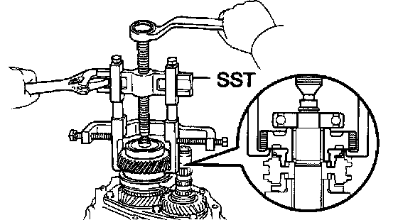
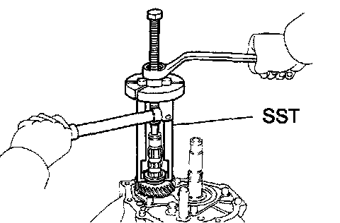
b. Using SST, remove the rear radial ball bearing and 6th driven gear.
SST 09950-40011 (09951-04010, 09952-04010, 09953-04030, 09954-04010, 09955-04021, 09957-04010,09958-04011)

HINT: At the time of reassembly, please refer to the following items.
^ Using SST and a hammer, drive In the 6th driven gear.
SST 09325-12010
NOTICE: Be sure to install the 6th driven gear in the correct direction, as shown in the illustration.

^ Set SST to the rear radial ball bearing inner race securely, drive in the bearing with a hammer.
SST 09517-12010
c. Remove the spacer.

15. REMOVE INPUT SHAFT REAR RADIAL BALL BEARING AND 6TH GEAR
a. Using 2 screwdrivers and a hammer, tap out the snap ring.

HINT: At the time of reassembly, please refer to the following item.
^ Select a snap ring from the table that will make the thrust clearance of the No.3 clutch hub less than 0.1 mm (0.0039 inch).
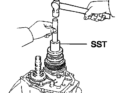
b. Using SST, remove the rear radial ball bearing and 6th gear.
SST 09950-40011 (09951-04010, 09952-04010, 09953-04030, 09954-04010, 09955-04021, 09957-04010, 09958-04011)
HINT: At the time of reassembly, please refer to the following item.
^ Set SST to the rear radial ball bearing inner race securely, drive in the bearing with a hammer.
SST 09517-12010
c. Remove the needle roller bearing and spacer.

16. REMOVE NO. 3 SYNCHRONIZER RING (FOR 6TH GEAR)
NOTICE: At the time of reassembly, please refer to the following items.
^ Align the No. 3 synchronizer ring slots with the No. 3 shifting keys.
^ Distinguish the No. 3 synchronizer ring (for the 6th gear) by the teeth on the synchronizer ring.
17. REMOVE NO. 3 GEAR SHIFT PORK AND NO. 3 HUB SLEEVE
Remove the bolt, No. 3 gear shift fork and No. 3 hub sleeve.
Sealant: Part No. 08833-00080, THREE BOND 1344, LOCTITE 242 or equivalent
Torque: 16 Nm (160 kgf-cm, 12 ft. lbs.)

18. INSPECT 5TH GEAR THRUST CLEARANCE
Using a dial indicator, measure the thrust clearance.
Standard clearance: 0.10 - 0.62 mm (0.0039 - 0.0244 inch)
Maximum clearance: 0.62 mm (0.0244 inch)

19. INSPECT 5TH GEAR RADIAL CLEARANCE
Using a dial indicator, measure the radial clearance.
Standard clearance: 0.015 - 0.056 mm (0.0006 - 0.0022 inch)
Maximum clearance: 0.056 mm (0.0022 inch)
If the clearance exceeds the maximum, replace the gear, needle roller bearing or shaft.
20. REMOVE 5TH GEAR, NO. 3 SYNCHRONIZER RING (FOR 5TH GEAR) AND NO. 3 CLUTCH HUB ASSEMBLY
a. Using 2 screwdrivers and a hammer, tap out the snap ring.

HINT: At the time of reassembly, please refer to the following item.
Select a snap ring from the table that will make the thrust clearance of the No.3 clutch hub less than 0.1 mm (0.0039 inch).

b. Using SST, remove the No. 3 clutch hub assembly.
SST 09950-30012 (09951-03010, 09953-03010), 09950-50013 (09954-05031)

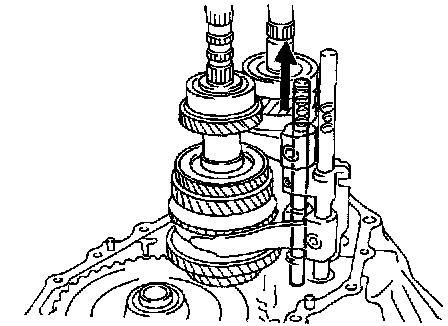
HINT: At the time of reassembly, please refer to the following items.
^ Before driving in the No.3 clutch hub assembly and input shaft rear radial ball bearing, place the suitable sized wooden block on the rear side of the input shaft, as shown in the illustration. When driving them in, fix the input shaft firmly so that it is not pushed downward. Otherwise the input shaft center bearing is overloaded, it might be damaged.

^ Using SST and a hammer, drive in the No. 3 clutch hub assembly.
SST 09612-22011
NOTICE:
^ Align the No. 3 synchronizer ring slots with the No. 3 shifting keys.
^ Be sure to install the No.3 clutch hub assembly in the correct direction, as shown in the illustration.

c. Remove the No. 3 synchronizer ring (for the 5th gear) and 5th gear from the input shaft.
NOTICE: At the time of reassembly, please refer to the following item.
Distinguish the No. 3 synchronizer ring (for the 5th gear) by the teeth on the synchronizer ring.
d. Using 2 screwdrivers and a hammer, tap out the snap ring.
e. Remove the needle roller bearing and 2 spacers.
21. REMOVE 5TH DRIVEN GEAR
Using SST, remove the 5th driven gear.
SST 09950-30012 (09951-03010, 09953-03010, 09954-03010, 09955-03021)

HINT:
At the time of reassembly, please refer to the following item.
Using SST and a hammer, drive in the 5th driven gear.
SST 09612-22011
22. REMOVE REAR BEARING RETAINER
Remove the 5 bolts and rear bearing retainer.
Sealant: Part No. 08833-00080, THREE BOND 1344, LOCTITE 242 or equivalent
Torque: 27 Nm (280 kgf-cm, 20 ft. lbs.)

23. REMOVE BEARING SNAP RING
Using a snap ring expander, remove the 2 snap rings.
HINT: If it is difficult to remove and install the snap rings, pull up the shafts.

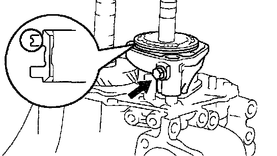
24. REMOVE REVERSE IDLER GEAR SHAFT LOCK BOLT AND GASKET
Sealant: Part No. 08833-00080, THREE BOND 1344, LOCTITE 242 or equivalent
Torque: 29 Nm (300 kgf-cm, 22 ft. lbs.)
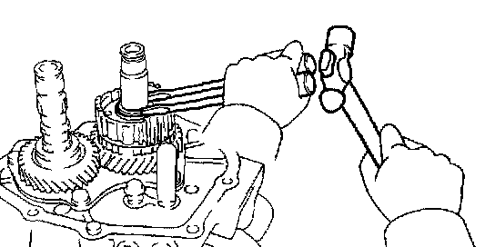
25. REMOVE SNAP RING FROM NO. 2 SHIFT FORK SHAFT
Using 2 screwdrivers and a hammer, tap out the snap ring.

26. REMOVE STRAIGHT SCREW PLUG, SEAT, SPRING AND BALL
a. Using a hexagon wrench, remove the 3 straight screw plugs.
Sealant: Part No. 08833-00080, THREE BOND 1344, LOCTITE 242 or equivalent
Torque: 25 Nm (250 kgf-cm, 18 ft. lbs.)
b. Using a magnetic finger, remove the 3 seats, springs and balls.
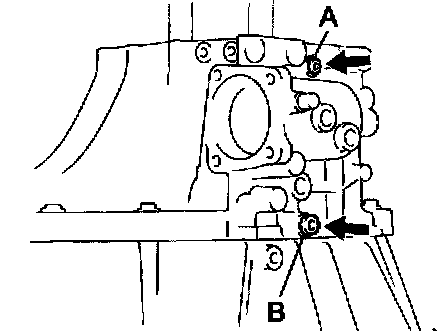
27. REMOVE STRAIGHT SCREW PLUG
Using a hexagon wrench, remove the 2 straight screw plugs
Sealant: Part No. 08833-00080, THREE BOND 1344, LOCTITE 242 or equivalent
Torque:
Plug A: 13 Nm (130 kgf-cm, 9 ft. lbs.)
Plug B: 39 Nm (400 kgf-cm, 29 ft. lbs.)

28. REMOVE TRANSMISSION CASE
a. Remove the 16 bolts.
Torque: 29 Nm (300 kgf-cm, 22 ft. lbs.)
b. Carefully tap the transmission case with a plastic hammer and remove it.
HINT:
At the time of reassembly, please refer to the following item.
Apply FIPG to the transaxle case side, as shown in the illustration.
FIPG: Part No. 08826-00090, THREE BOND 1281 or equivalent

29. REMOVE OIL RECEIVER PIPE
Remove the 2 bolts and oil receiver pipes from the transmission case.
Torque: 17 Nm (175 kgf-cm, 13ft. lbs.)
NOTICE: At the time of reassembly, please refer to the following items.
^ Prevent the oil receiver pipes from being deformed.
^ Install the oil receiver pipes while placing it against the transmission case, as shown in the illustration.
30. REMOVE REVERSE SHIFT ARM BRACKET
Remove the 2 bolts and reverse shift arm bracket.
Torque: 17 Nm (175 kgf-cm, 13 ft. lbs.)
NOTICE: At the time of reassembly, please refer to the following items.
^ Set the pin on the top of the reverse shift arm into a groove on the reverse idler gear.
^ Fit the claw of the reverse shift arm bracket with the notch of the input shaft front bearing.

31. REMOVE REVERSE IDLER GEAR, THRUST WASHER AND SHAFT
NOTICE: At the time of reassembly, please refer to the following item.
Install the reverse idler gear, thrust washer and shaft, as shown in the illustration.

32. REMOVE GEAR SHIFT FORK SHAFT SNAP RING
Using 2 screwdrivers and a hammer, tap out the 2 snap rings from the No. 1 and No. 3 gear shift fork shafts.

33. REMOVE NO. 1 GEAR SHIFT HEAD, NO. 1 AND NO. 2 GEAR SHIFT FORKS 3 SET BOLTS
Sealant: Part No. 08833-00080, THREE BOND 1344, LOCTITE 242 or equivalent
Torque: 16 Nm (160 kgf-cm, 12 ft. lbs.)

NOTICE:
At the time of reassembly, please refer to the following item.
Make sure that the 3 gear shift heads are positioned, as shown in the illustration.
34. REMOVE NO. 2 GEAR SHIFT FORK SHAFT
Remove the No. 2 gear shift fork shaft from the No. 2 gear shift fork, No. 1 gear shift head, No 1 gear shift fork, reverse shift fork and transaxle case.

35. REMOVE NO. 1 GEAR SHIFT FORK SHAFT
Remove the No. 1 gear shift fork shaft from the No. 1 gear shift fork and transaxle case.

36. REMOVE NO. 1 GEAR SHIFT HEAD

37. REMOVE NO. 1 GEAR SHIFT FORK FROM REVERSE GEAR GROOVE

38. REMOVE NO. 3 GEAR SHIFT FORK SHAFT AND REVERSE SHIFT FORK
a. Remove the No. 3 gear shift fork shaft from the reverse shift fork and transaxle case.
b. Remove the reverse shift fork.

39. REMOVE NO. 2 GEAR SHIFT FORK FROM NO. 2 HUB SLEEVE GROOVE
40. REMOVE INPUT AND OUTPUT SHAFTS TOGETHER FROM TRANSAXLE CASE
41. REMOVE DIFFERENTIAL CASE ASSEMBLY
NOTICE:
At the time of reassembly, please refer to the following item.
Before reassembly, inspect the differential tapered roller bearing preload.
42. REMOVE MAGNET FROM TRANSAXLE CASE

43. DISASSEMBLE NO. 3 CLUTCH HUB ASSEMBLY
a. Using a screwdriver, remove the 2 shifting key springs
NOTICE:
At the time of reassembly, please refer to the following item.
Position the shifting key springs so that their end gaps are not aligned.
b. Remove the 3 No 3 shifting keys from the No 3 clutch hub.
INSPECTION
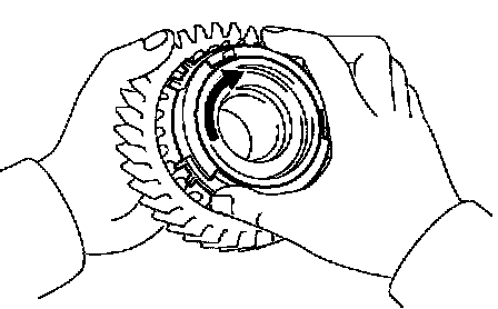
1. INSPECT 5TH AND 6TH GEARS SYNCHRONIZER RING
a. Check for wear or damage.
b. Check the braking effect of the synchronizer ring. Turn the synchronizer ring in one direction while pushing it to the gear cone. Check that the ring locks.
If the braking effect is insufficient, apply a small amount of the fine lapping compound between the synchronizer ring and gear cone. Lightly rub the synchronizer ring and gear cone together.
NOTICE: Ensure the fine lapping compound is completely washed off after rubbing.
c. Check again the braking effect of the synchronizer ring.

d. Using a feeler gauge, measure the clearance between the synchronizer ring back and gear spline end.
Minimum clearance: 0.75 mm (0.0295 inch)
If the clearance is less than the minimum, replace the synchronizer ring, and apply a small amount of the fine lapping compound on gear cone.
NOTICE: Ensure the fine lapping compound is completely washed off after rubbing.

2. INSPECT GEAR SHIFT FORK AND HUB SLEEVE CLEARANCE
Using a feeler gauge, measure the clearance between the hub sleeve and gear shift fork.
Maximum clearance: 0.89 mm (0.035 inch)
If the clearance exceeds the maximum, replace the gear shift fork or hub sleeve.
3. REMOVE TRANSAXLE CASE RECEIVER
Remove the bolt and transaxle case receiver from the transaxle case.
4. IF NECESSARY, REPLACE INPUT SHAFT FRONT BEARING AND OIL SEAL
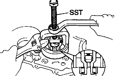
a. Using SST, remove the input shaft front bearing.
SST 09612-65014

b. Using a screwdriver, remove the oil seal.

c. Using SST and a hammer, drive in a new oil seal.
SST 09950-60010 (09951-00360), 09950-70010 (09951-07150)
Drive in depth: 15.8 ± 0.2 mm (0.622 ± 0.008 inch)
d. Coat the lip of the oil seal with MP grease.

e. Using SST and a press, install a new input shaft front bearing.
SST 09950-60010 (09951-00400), 09950-70010 (09951-07150)
Drive in depth: 0 - 0.3 mm (0 - 0.012 inch)
NOTICE: Be sure to install a new bearing in the correct direction, as shown in the illustration.
5. IF NECESSARY, REPLACE OUTPUT SHAFT FRONT BEARING AND OUTPUT SHAFT COVER
a. Remove the bolt and bearing lock plate.
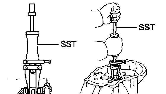
b. Using SST, pull out the output shaft front bearing.
SST 09308-00010

c. Remove the output shaft cover.
d. Install the output shaft cover.
NOTICE: Install the output shaft cover projection into the case side hollow.

e. Using SST and a press, install a new output shaft front bearing.
SST 09950-60010 (09951-00560), 09950-70010 (09951-07150)
NOTICE: Be sure to install a new bearing in the correct direction, as shown in the illustration.
f. Install the bearing lock with the bolt.
Torque: 11 Nm (115 kgf-cm, 8 ft. lbs.)
6. INSTALL TRANSAXLE CASE RECEIVER
Install the transaxle case receiver to the transaxle case with the bolt.
Torque: 11 Nm (115 kgf-cm, 8 ft. lbs.)
7. IF NECESSARY, REPLACE TRANSMISSION CASE BUSHING

a. Using a socket wrench (12 mm), extension bar and plastic hammer, drive out the bushing.
NOTICE: When driving out the bushing, be careful not to damage the transmission case by the socket wrench.
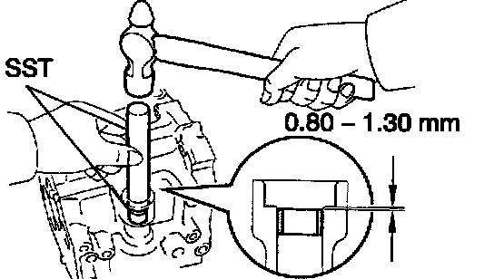
b. Using SST and a hammer, drive in a new bushing.
SST 09950-60010 (09951-00180), 09950-70010 (09951-07100)
Drive in depth: 0.80 - 1.30 mm (0.0315 - 0.0512 inch)
8. IF NECESSARY, REPLACE TRANSMISSION CASE OIL SEAL
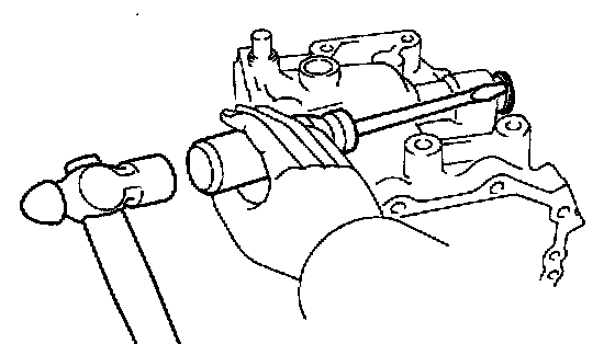
a. Using a screwdriver and hammer, drive out the oil seal.
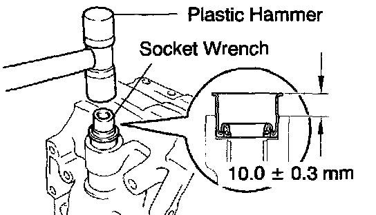
b. Using a socket wrench (17 mm) arid plastic hammer, drive in a new oil seal.
Drive in depth: 10.0 ± 0.3 mm (0.394 ± 0.012 inch)
c. Coat the lip of the oil seal with MP grease.