Voltage Converter: Testing and Inspection
ON-VEHICLE INSPECTION1. INSPECT INVERTER
a. Turn the IG switch OFF and disconnect the 4 connectors.
b. Apply battery positive voltage to connector B terminal 5 (IGCT) on the inverter side through a fuse, and battery negative voltage to connector B terminal 6 (GND).
Converter And Inverter Assembly - Connector View/Pinouts:
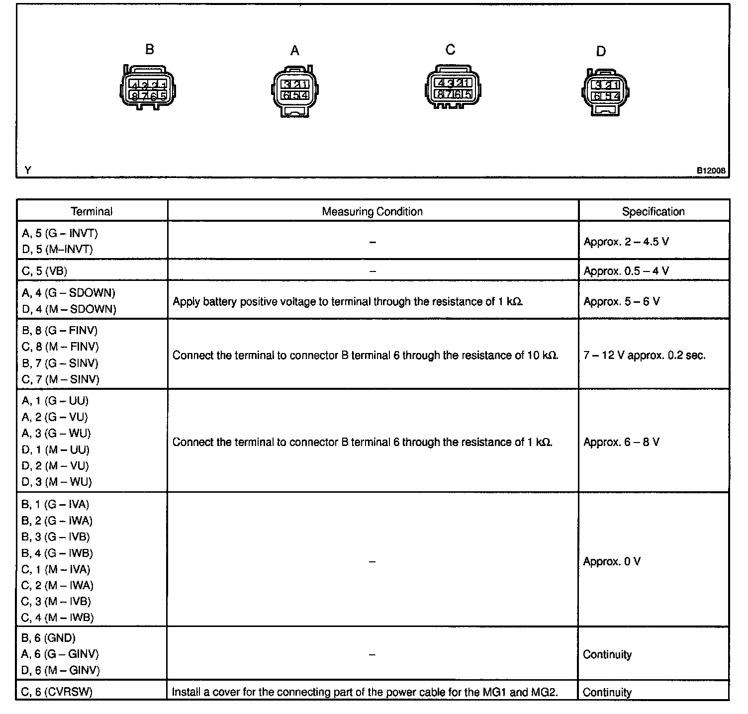
c. Measure the voltage and resistance between each terminal shown and ground.
2. INSPECT CONVERTER
a. Function check
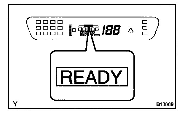
Measure the voltage of an auxiliary battery terminal when the "READY" lamp is OFF and ON.
READY lamp is OFF: Approx. 12 V
READY lamp Is ON: Approx. 14 V
b. Output current check
1. Disconnect the MG2 power cable from the inverter.
2. Install AC/DC 400 A probe to the wire harness of the IP connector of the converter.
3. Connect the MG2 power cable to the inverter.
4. With the READY lamp ON, operate electric devices one by one and measure the output current.
Standard: 100 A or less
HINT: If more than 100 A is shown momentarily, check for the followings.
- Ground short of electric device.
- Overload caused by installation of excessive device.
- PTC heater operation.