Installation
2AZ-FE ENGINE MECHANICAL: TIMING CHAIN:
INSTALLATION
1. INSTALL NO. 2 CHAIN SUB-ASSEMBLY

(a) Set the crankshaft key into the left horizontal position.
(b) Turn the drive shaft so that the cutout faces upward.

(c) Align the yellow mark links with the timing marks of each gear as shown in the illustration.
(d) Install the sprockets onto the crankshaft and oil pump shaft with the chain wrapped on the gears.
(e) Temporarily tighten the oil pump drive shaft sprocket with the nut.

(f) Insert the damper spring into the adjusting hole, and then install the chain tensioner plate with the bolt.
Torque: 12 Nm (122 kgf-cm, 9 ft-lbf)

(g) Align the adjusting hole of the oil pump drive shaft sprocket with the groove of the oil pump.
(h) Insert a 4 mm diameter bar into the adjusting hole of the oil pump drive shaft gear to lock the gear in position, and then tighten the nut.
Torque: 30 Nm (301 kgf-cm, 22 ft-lbf)

(i) Rotate the crankshaft clockwise by 90°, and align the crankshaft key to the top.
2. INSTALL CRANKSHAFT TIMING SPROCKET
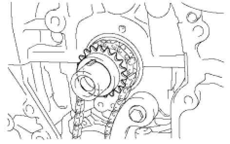
(a) Install the crankshaft timing sprocket.
3. INSTALL NO. 1 CHAIN VIBRATION DAMPER
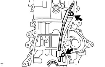
(a) Install the chain vibration damper with the 2 bolts.
Torque: 9.0 Nm (92 kgf-cm, 80 in-lbf)
4. INSTALL CHAIN SUB-ASSEMBLY
(a) Set the No. 1 cylinder to TDC/compression.

(1) Turn the camshafts with a wrench (using the hexagonal lobe) to align the timing marks of the camshaft timing gear with each timing mark located on the No. 1 and No. 2 bearing caps as shown in the illustration.

(2) Using the crankshaft pulley bolt, turn the crankshaft to position with the key on the crankshaft upward.

(b) Install the chain onto the crankshaft timing sprocket with the gold or pink mark link aligned with the timing mark on the crankshaft.

(c) Using SST and a hammer, tap in the crankshaft timing sprocket.
SST: 09309-37010

(d) Align the gold or yellow link with each timing mark located on the camshaft timing gear and sprocket, then install the chain.
5. INSTALL CHAIN TENSIONER SLIPPER
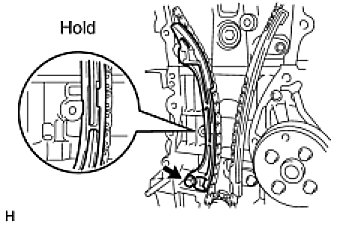
(a) Install the chain tensioner slipper with the bolt.
Torque: 19 Nm (194 kgf-cm, 14 ft-lbf)
6. INSTALL TIMING CHAIN GUIDE
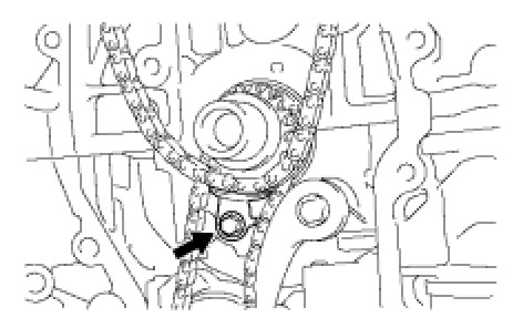
(a) Install the timing chain guide with the bolt.
Torque: 9.0 Nm (92 kgf-cm, 80 in-lbf)
7. INSTALL NO. 1 CRANKSHAFT POSITION SENSOR PLATE
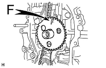
(a) Install the sensor plate with the "F" mark facing forward.
8. INSTALL TIMING CHAIN CASE OIL SEAL (Installation)
9. INSTALL TIMING CHAIN COVER SUB-ASSEMBLY (Installation)
10. INSTALL V-RIBBED BELT TENSIONER ASSEMBLY
(a) Spring type:
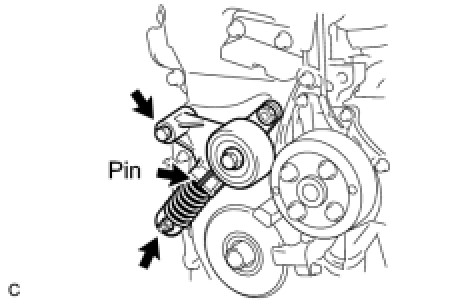
(1) Install the V-ribbed belt tensioner to the engine by first tightening the bolt and then tightening the nut.
Torque: 60 Nm (607 kgf-cm, 44 ft-lbf)
NOTE: When replacing the V-ribbed belt tensioner with a new one, do not pull out the pin.
(b) Except spring type:
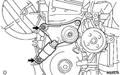
(1) Install the tensioner with the bolt and nut.
Torque: 60 Nm (607 kgf-cm, 44 ft-lbf)
NOTE: Do not lift the engine more than necessary.
11. INSTALL ENGINE MOUNTING BRACKET RH
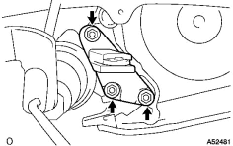
(a) Install the engine mounting bracket with the 3 bolts.
Torque: 54 Nm (551 kgf-cm, 40 ft-lbf)
12. INSTALL ENGINE MOUNTING INSULATOR
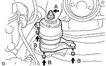
(a) Raise the engine and install the engine mounting insulator RH.
(b) Install the engine mounting insulator RH with the 4 nuts.
Nut A - Torque: 95 Nm (969 kgf-cm, 70 ft-lbf)
Nut B - Torque: 87 Nm (888 kgf-cm, 64 ft-lbf)
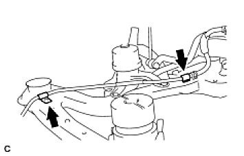
(c) Install the steering gear return tube clamps to the frame with the 2 bolts.
Torque: 8.0 Nm (80 kgf-cm, 69 in-lbf)
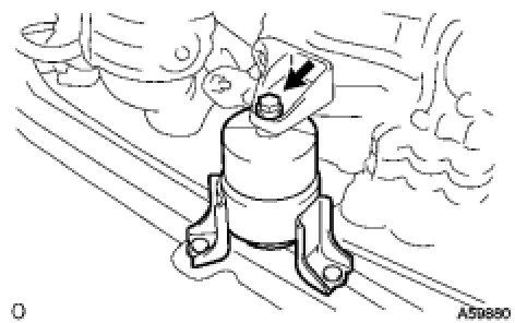
(d) Install the engine mounting insulator FR with the bolt.
Torque: 87 Nm (888 kgf-cm, 64 ft-lbf)
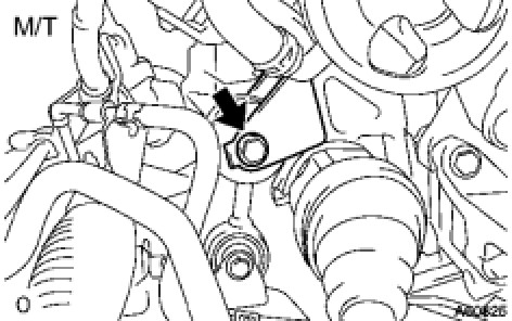
(e) M/T:
Install the engine lateral control rod with the bolt.
Torque: 89 Nm (910 kgf-cm, 66 ft-lbf)
13. INSTALL OIL PAN SUB-ASSEMBLY
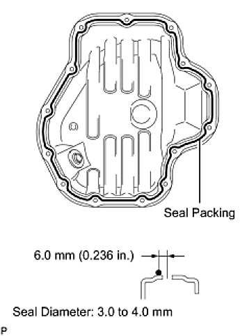
(a) Remove any old packing material and be careful not to drop any oil on the contact surfaces of the cylinder block and oil pan.
(b) Apply a continuous bead of seal packing (Diameter 3.0 to 4.0 mm (0.118 to 0.157 in.)) as shown in the illustration.
Seal packing:
Toyota Genuine Seal Packing Block, Three Bond 1207B or Equivalent
NOTICE:
- Remove any oil from the contact surfaces.
- Install the oil pan within 3 minutes after applying seal packing.
- Do not start the engine for at least 2 hours after installing.
(c) Install the oil pan to the cylinder block.

(d) Uniformly tighten the 12 bolts and 2 nuts in the sequence shown in the illustration.
Torque: 9.0 Nm (92 kgf-cm, 80 in-lbf)
14. INSTALL CRANK POSITION SENSOR (Installation)
15. INSTALL CRANKSHAFT PULLEY (Installation)
16. INSTALL NO. 1 CHAIN TENSIONER ASSEMBLY
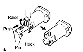
(a) Release the ratchet pawl, then fully push in the plunger and hook the hook to the pin so that the plunger is in the position shown in the illustration.
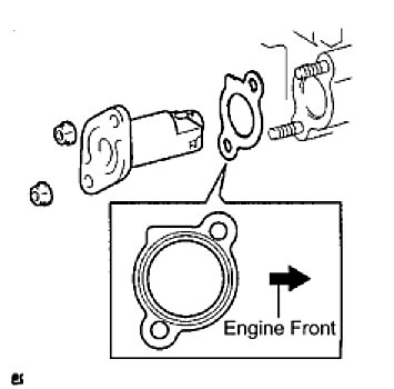
(b) Install a new gasket and the chain tensioner with the 2 nuts.
Torque: 9.0 Nm (92 kgf-cm, 80 in-lbf)
NOTE: If the hook releases the plunger while the chain tensioner is being installed, set the hook again.
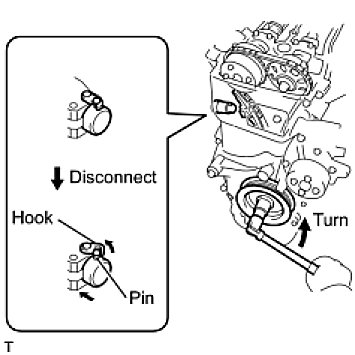
(c) Turn the crankshaft counterclockwise, then disconnect the plunger knock pin from the hook.
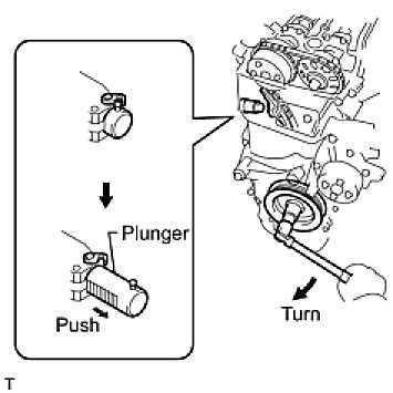
(d) Turn the crankshaft clockwise, then check that the plunger is extended.
17. INSTALL CYLINDER HEAD COVER SUB-ASSEMBLY
(a) Remove any old packing material from the contact surface.
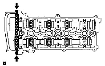
(b) Apply seal packing to the 2 locations shown in the illustration.
Seal packing:
Toyota Genuine Seal Packing Block, Three Bond 1207B or Equivalent
- Remove any oil from the contact surface.
- Install the cylinder head cover within 3 minutes of applying seal packing.
- Do not add engine oil for at least 2 hours after installing the cylinder head cover.
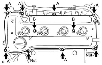
(c) Install the cylinder head cover with the 8 bolts and 2 nuts.
Bolt A - Torque: 11 Nm (112 kgf-cm, 8 ft-lbf)
Bolt B - Torque: 14 Nm (143 kgf-cm, 10 ft-lbf)
Nut - Torque: 11 Nm (112 kgf-cm, 8 ft-lbf)
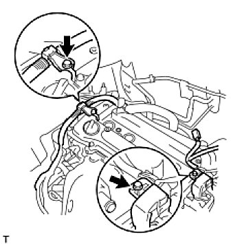
(d) Install the 2 engine wires with the 2 bolts.
Torque: 8.4 Nm (86 kgf-cm, 74 in-lbf)
18. INSTALL NO. 2 VENTILATION HOSE
19. INSTALL VENTILATION HOSE
20. INSTALL IGNITION COIL ASSEMBLY
(a) Install the 4 ignition coils with the 4 bolts.
Torque: 9.0 Nm (92 kgf-cm, 80 in-lbf)
21. INSTALL VANE PUMP ASSEMBLY (Installation)
22. INSTALL GENERATOR ASSEMBLY (Installation)
23. INSTALL V-RIBBED BELT (Installation)
24. INSTALL NO. 2 ENGINE MOUNTING BRACKET RH (Installation)
25. INSTALL ENGINE MOVING CONTROL ROD SUB-ASSEMBLY (Installation)
26. INSTALL NO. 2 ENGINE MOUNTING STAY RH (Installation)
27. INSTALL FRONT EXHAUST PIPE ASSEMBLY
HINT: (Installation).
28. ADD ENGINE OIL
29. CONNECT CABLE TO NEGATIVE BATTERY TERMINAL (Installation)
30. CHECK FOR ENGINE OIL LEAKS
31. CHECK FOR EXHAUST GAS LEAKS
32. CHECK IGNITION TIMING (Engine)
33. INSTALL FRONT FENDER APRON SEAL RH
34. INSTALL ENGINE UNDER COVER LH
35. INSTALL ENGINE UNDER COVER RH
36. INSTALL FRONT WHEEL RH
37. INSTALL NO. 1 ENGINE COVER SUB-ASSEMBLY (Installation)