Exhaust Gas Recirculation: Diagrams
EGR sytem, component layout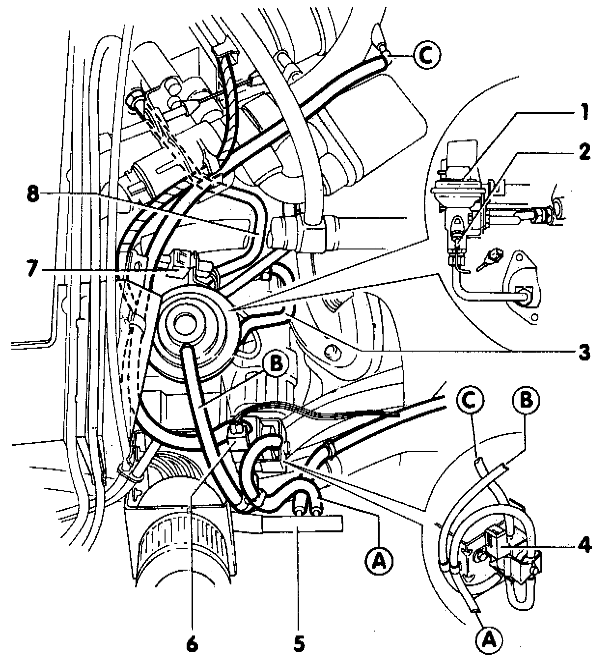
NOTE: The function of the EGR system is checked via the Motronic On Board Diagnostic system.
- components identified by an * can be checked using On Board Diagnostic
- components identified by two ** can be checked using Output DTM (Diagnostic Test Mode)
- always replace any seals or 0-rings when performing assembly work
- ensure that all vacuum lines and hose connections are tight
- ensure that vacuum lines are not plugged or bent
1 - EGR valve
- checking Testing and Inspection
2 - EGR temperature sensor (G 98)*
- 2O Nm (15 ft lb)
3 - Exhaust inlet tube
4 - EGR frequency valve (N 18)**
5 - Connector port
for intake manifold pressure measurement
6 - Harness connector for EGR frequency valve (N 018)
7 - Harness connector for (G 098) temperature sensor
8 - Exhaust outlet tube
NOTE:
When repairing a connection to or repairing an engine management system component (i.e.. Knock Sensor, Mass Air Flow Sensor, Throttle Position Sensor, etc.) ensure the mating connector terminals are made of the same material and that the terminals are not damaged or corroded.
If the component has gold-plated terminals but the mating harness does not, replace the mating harness connector terminals with gold-plated terminals. If the mating harness has gold-plated terminals but the component does not, replace the component.