Ignition System: Description and Operation
Motronic Fuel and Ignition system, component layout (ignition portion only)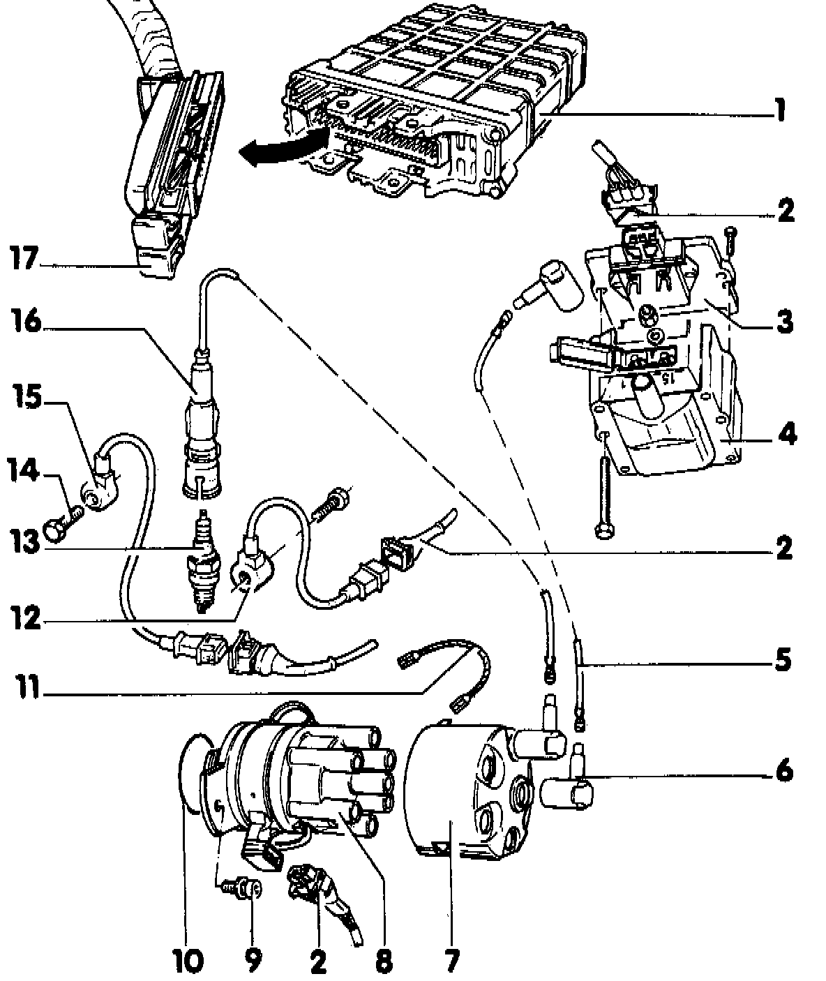
- Safety precautions, Service Precautions
NOTE: Components marked with an asterisk (*) are checked via the VAG 1551 scan tool.
1 - Engine control module (J 220)*
2 - Harness connector for ignition coil
3 - Ignition coil power output stage (N 157)
4 - Ignition coil (N 152)
5 - Ignition wire
6 - RFI suppression connector
7 - RFI suppression cap
8 - Distributor cap
9 - 10 Nm (7 ft lb)
10 - O-ring
replace if damaged
11 - Ground connector
12 - Knock sensor II (G 66)*
13 - Spark plug
- 25 Nm (18 ft lb)
- use 3122 B adaptor to remove and install
14 - 20 Nm (15 ft lb)
15 - Knock Sensor I (G 61)*
16 - Spark plug connector
use 3277 adaptor to remove and insert
17 - Harness connector for engine control module
CAUTION: Do NOT disconnect until ignition has been switched oft for at least 20 seconds
NOTE:
When repairing a connection to or replacing an engine management system component (i.e. Knock Sensor, Mass Air Flow Sensor, Throttle Position Sensor, etc.), ensure the mating connector terminals are made of the same material and that the terminals are not damaged or corroded.
If the component has gold plated terminals but the mating harness does not, replace the mating harness connector terminals with gold-plated terminals. If the mating harness has gold plated terminals but the component does not, replace the component.