Ignition System: Locations
Ignition System Components, Assembly Overview
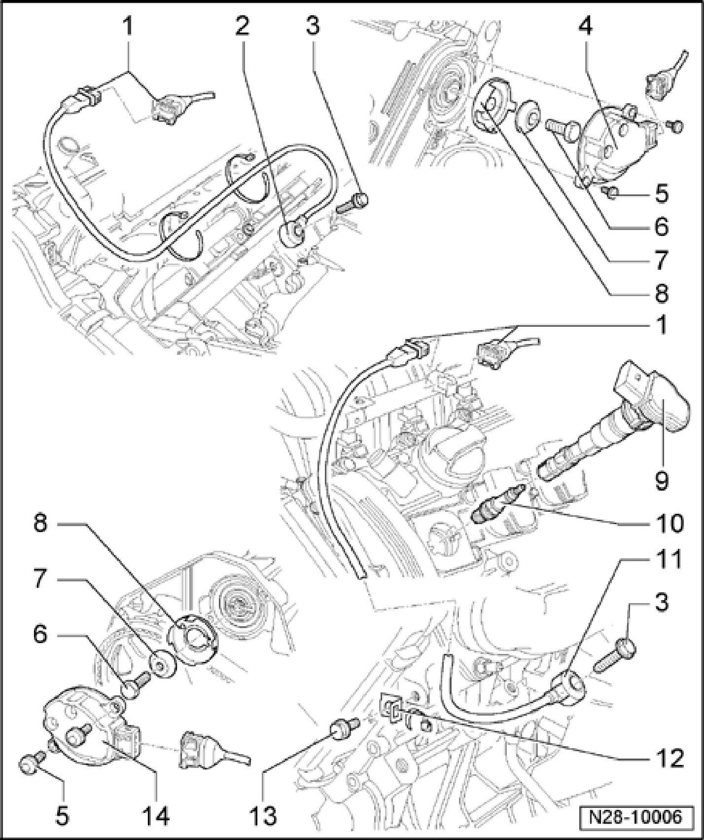
1 - Connection for knock sensor
- Secured to fuel rail with retaining strap
2 - Knock sensor 1 G61
- Sensor contacts and connector contacts gold plated
- Knock sensor wiring fastened to coolant pipe
3 - 20 Nm
- Torque setting influences function of knock sensor
4 - Camshaft position (CMP) sensor 2 G163
- For intake camshaft, bank 2
- Sensor contacts and connector contacts gold plated
5 - 10 Nm
6 - 25 Nm
7 - Washer
- Conical
- Note installation position
8 - Hood
- For Camshaft Position (CMP) Sensor
- Observe installed location
9 - Ignition coil with power output stage (N70, N127, N291, N292, N323, N324, N325, N326)
- Remove and install using Ignition Coil Puller T40039 only.
10 - Spark plug, 30 Nm
- Remove and install using Spark Plug Removal Tool 3122B.
- Type and spark plug gap
11 - Knock sensor 2 G66
12 - Bracket
13 - 10 Nm
14 - Camshaft Position (CMP) sensor G40
- For intake camshaft, bank 1
- Sensor contacts and connector contacts gold plated