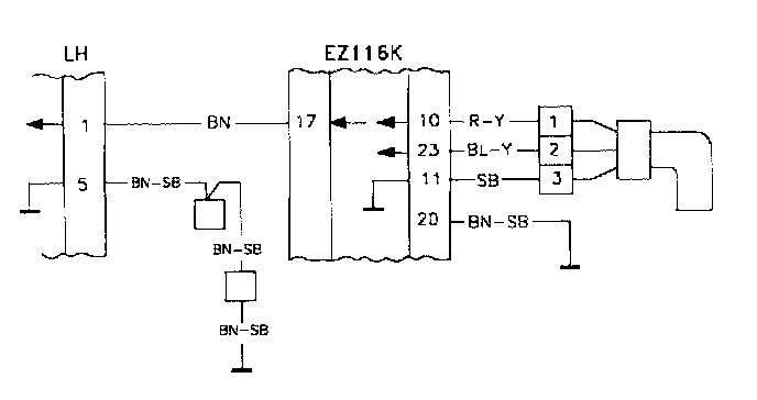
MFI #1, DI #17, DI #23 No Engine Speed Signal
UD. MFI#1, DI#17, DI#23
MFI#1 No engine speed signal
DI#17 No engine speed signal
Fault message conditions:
If the voltage has not been above 9 V for a certain period a fault message is recorded. This period varies with engine speed and is about 200 ms when the engine is idling. When the engine is being started the message is recorded when there is power from the ignition but the engine speed signal is below 9 V after 10 seconds.
Fault causes:
Break or grounding in the wiring between the control modules.
Break or short circuit in the RPM sensor wiring. Defective RPM sensor.
Fault symptoms:
The engine will not start.
If the fault is intermittent the engine will stop or run rough.
DI#23 No RPM Sensor Signal
Fault conditions:
Engine speed over 1500 rpm and ignition off.
If voltage has not been above 2.5 V. for a certain period a fault message is recorded. This period varies with engine speed and is about 120 ms when the engine is idling.
Fault causes:
Break or grounding in the tachometer wiring.
Contact resistance.
Detective RPM sensor.
Fault symptoms:
The engine will not start.
If the fault is intermittent the engine will stop or run rough.
UD1
Checking The RPM Sensor
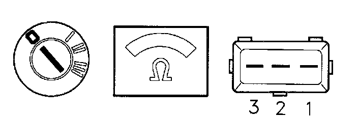
-Ignition off.
Connect an ohmmeter between 1 and 2 on the RPM sensor.
Engine speed sensor 1 389 567-7 (early models):
The ohmmeter should read about 240 OHMS and a maximum of 400 OHMS when the engine is warm.
Engine speed sensor 3 547 847-8 (late models):
The ohmmeter should read about 170 OHMS and a maximum of 350 OHMS when the engine is warm.
If this value Is OK
-Volvo ST, Test box UD2
If this value Is Incorrect
-Try using a new RPM sensor.
UD2
Volvo ST, Test Box

-Disconnect the ST.
-Connect the test box to the 1CM and check the GND points.
-Continue with checking GND point UD3.
UD3
Checking The RPM Sensor Signal
-Connect the control module to the test box.
-Re-install system fuse.
Connect a voltmeter between DI#10 and DI#23.
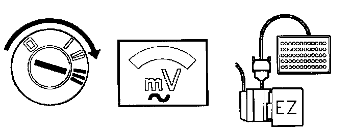
-Operate the starter motor.
The voltmeter should read at least 500 mV AC.
If this value is OK
1. Fault message DI#23:
Intermittent fault.
-Check the wiring between the RPM sensor and the control module for loose contacts.
2. Fault message DI#17 or MFI#1
-Check engine speed signal, DI UD4.
If the value is incorrect
-Check the wiring between the RPM sensor and the control module for breaks and grounding.
UD4
Checking The Engine Speed Signal, Ignition Control Module (ICM)
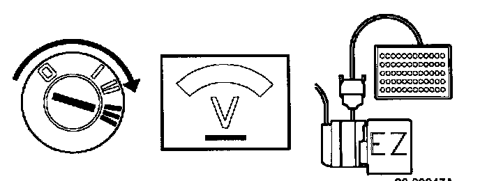
-Ignition on.
Connect a voltmeter between DI#17 and DI#20 (GND). The voltmeter should read battery voltage.
If this value Is OK
-Check the wiring between the control modules for breaks.
If the value Is incorrect
-Check the wiring between the control modules for grounding.