C. Repl. Termin. In the Connector For the (SRS) Control Module
C: Removing and installing the service cable harness from the connector to the supplemental restraint system control module (SRS)Removing the SRS control module connector
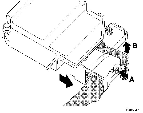
First press in the catch (A). Then fold the lock (B) forward. Remove the connector.
Disassembling the connector 2
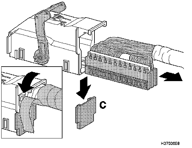
Partially remove the insulation tape from the connector and cable harness.
Slide the locking tab (C) out.
Pull the cable harness and connector out of the housing.
Checking the connectors and terminals 3
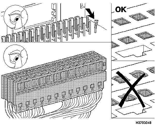
Check whether the openings in the connectors are damaged. The holes must be square. If one or more opening is deformed, the cable terminals must be checked more closely. To remove cable terminals, see method C step 6.
Check if the cable terminals are damaged. Compare all visible cable terminals. If one or more cable terminals look damaged, the entire cable harness must be replaced. See method B and/or D.
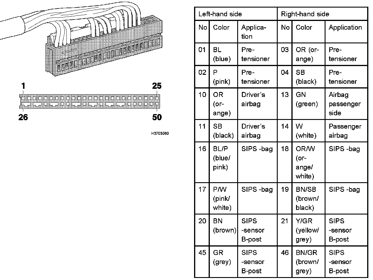
Connection overview, affects MY 2000 4
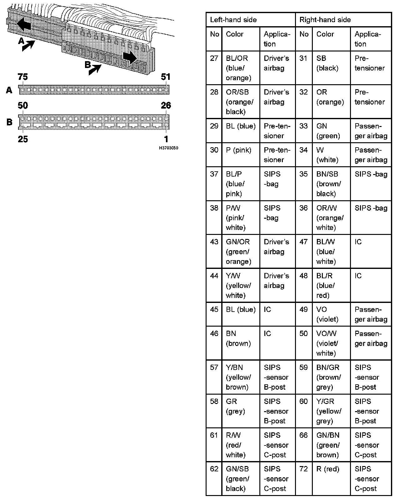
Connection overview, affects MY 2001- 5
Removing the cable terminals from the connectors 6
Note!
To avoid mixing up the cables, remove one cable at a time.
Note the position and color of the cable terminals for the connections being replaced.
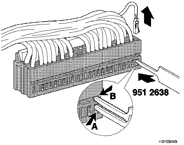
Use terminal removal tool 951 2638 to extract the cable terminals.
Narrow connector: Remove the cable terminal by first pressing in the lock (A) and then pulling the cable slightly. Then press in the lock (B) and pull out the cable.
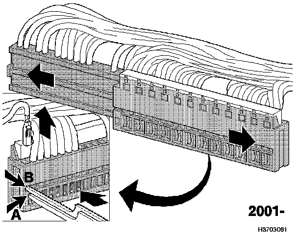
Wide connector (2001-): Disassemble the connector by sliding the halves apart. This is necessary to be able to remove the cable terminals.
Installing new cable terminals in the connectors 7
Use the cables in the service cable harness which are the same color as the cables being replaced. Position the cable terminals in the connector in the same terminals that they were in prior to removal.
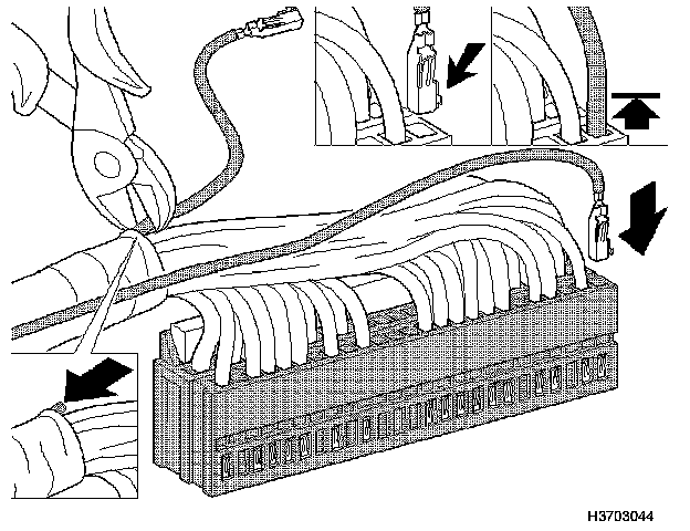
Place the terminal in the right position in the housing, see illustration.
Check that the cable terminals are secure by pulling the cable gently.
Slide the connectors together, (applies to MY 2001-). Pull the old cables as far out from the cable harness casing as possible. Cut off the cables as close to the casing as possible.
Press the cables into the casing without damage or sticking other parts.
Assembling the connector 8
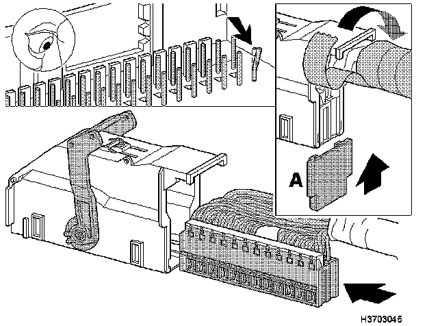
Check that the terminal pins on the supplemental restraint system control module (SRS) are undamaged. These must not be damaged or bent.
Slide the connector into the housing. Slide the locking tab (A) into place.
Replace the insulation and add extra tape to secure the cable harness to the housing.
Caution!
Do not connect the connector to the SRS control module.