Output Transistor Signal Test
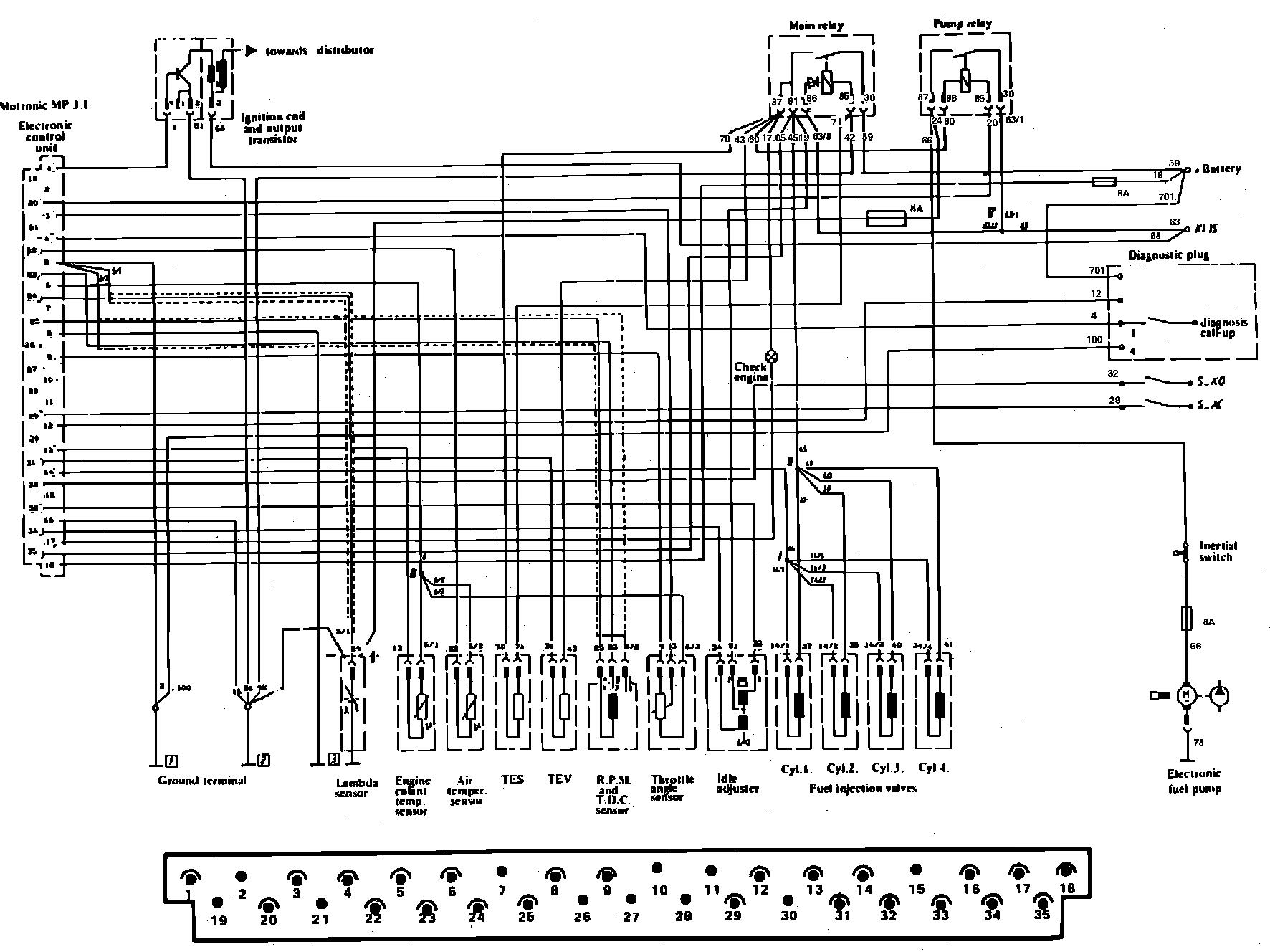
Refer to Fig. 5 when performing the following procedure.Fig. 5 Bosch Motronic Electronic Engine Control System Terminal Identification:
1. With output transistor connected, expose transistor connector by pushing back rubber insulator. Using a suitable digital voltmeter check battery voltage is present at terminals 2 and 3 by probing back side of connector. If no voltage reading is obtained, proceed as follows:
a. Check for 12 volts at ignition switch terminal 15.
b. Check ground connection terminal 2, and ground wire for continuity.
Fig. 6 Output Transistor Control Pulse:
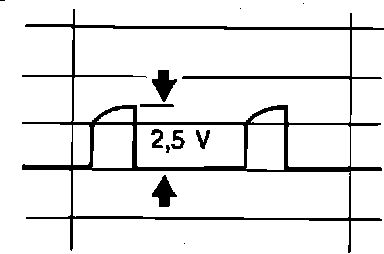
c. Using an oscilloscope, check control pulse at terminal 4 of output transistor is as shown in Fig. 6 with engine cranking and running.
d. If no pulse exists and connections and wiring check OK, replace ECU.
e. If all possible faults are eliminated and no spark exists, perform test procedures described under ``Output Transistor Test.''