Test Box, Connecting For Wiring Test
Test Box, Connecting For Wiring Test
Recommended special tools and equipment e.g.:
Vehicles with 80-pin control module
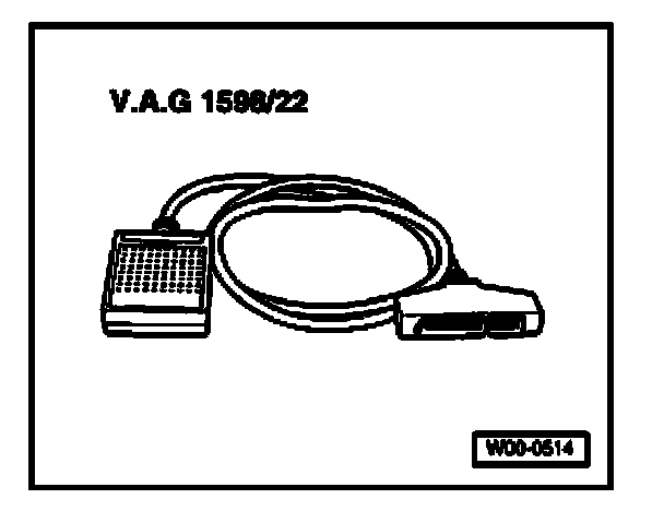
- V.A.G 1598/22 test box
Vehicles with 121-pin control module
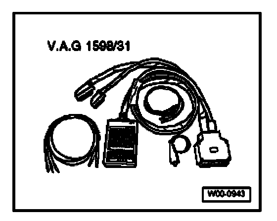
- V.A.G 1598/31 test box
Vehicles with 154-pin control module
- V.A.G 1598/42 test box
- V.A.G 1598/39-1 adapter cable
- V.A.G 1598/39-2 adapter cable
Continue for all vehicles
Requirement
- Ignition switched off.
Work sequence for control module for Diesel-Direct Fuel Injection System
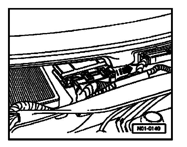
- Remove wiper arms and wind cowl
- Disengage connector from control module and disconnect.
Vehicles with 80-pin control module
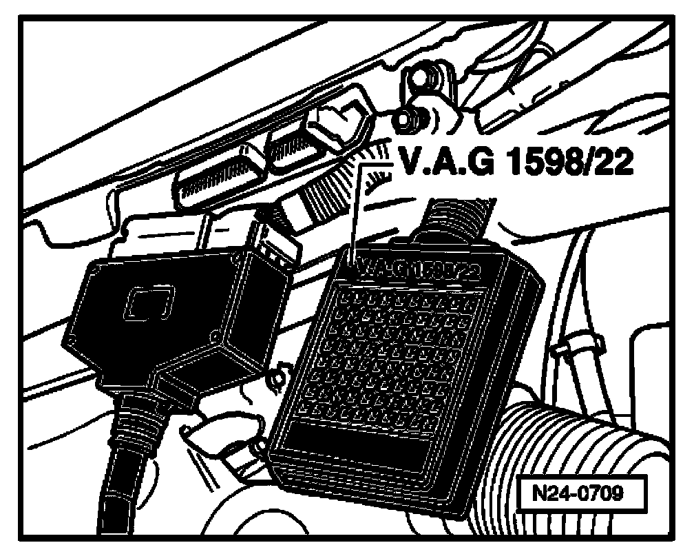
- Connect VAG1598/22 test box at control module wiring harness.
Vehicles with 121-pin control module
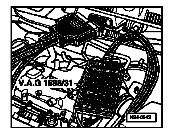
- Connect VAG1598/31 test box at control module wiring harness. The control module for Diesel-Direct fuel injection system is not connected.
Vehicles with 154-pin control module
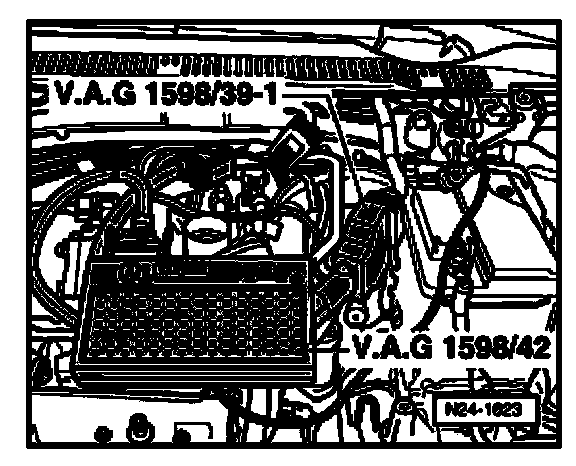
- Connect test box (V.A.G 1598/42) to control module wiring harness using adapter cable (V.A.G 1598/39-1 or V.A.G 1598/39-2). The control module for Diesel-Direct fuel injection system is not connected.
Continue for all vehicles
When harness connectors are disconnected from the control module for Diesel-Direct fuel injection system or the battery is disconnected, all adaptation values in the control module are erased. DTC memory content will remain intact however. If the engine is started after this, rough, uneven idle can result for a short time. In this case, the readiness code must be generated again. Monitors, Trips, Drive Cycles and Readiness Codes
Work procedure for Transmission Control Module (TCM)
- Remove wiper arms and wind cowl
- Open locking mechanism of connector in -direction of arrow- and disconnect from control module.
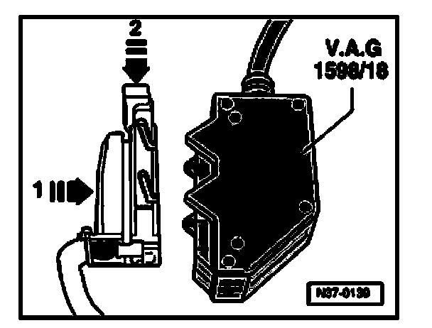
- Connect test box (V.A.G 1598/18) to control module wiring harness (arrow -1-) and engage (arrow -2-).