Campaign - DC to DC Converter Replacement
00-093March 6, 2001
Applies To:
2000 Insight - From VIN JHMZE1...YT004144 thru JHMZE1...YT005604
Product Update: DC-DC Converter
(Supersedes 00-093, dated November 21, 2000)
BACKGROUND
The DC-DC converter serves as the "alternator." Its purpose is to charge the 12V battery that powers the lighting, accessories, etc. The DC-DC converter has thermal protection to keep it from overheating. If the converter gets too hot, it shuts down and no longer charges the battery. When this happens, the Charging System indicator comes on to show the "no charge" condition.
In certain DC-DC converters, the internal temperature monitors are defective, causing the converter to shut down when there is no overheating.
CUSTOMER NOTIFICATION
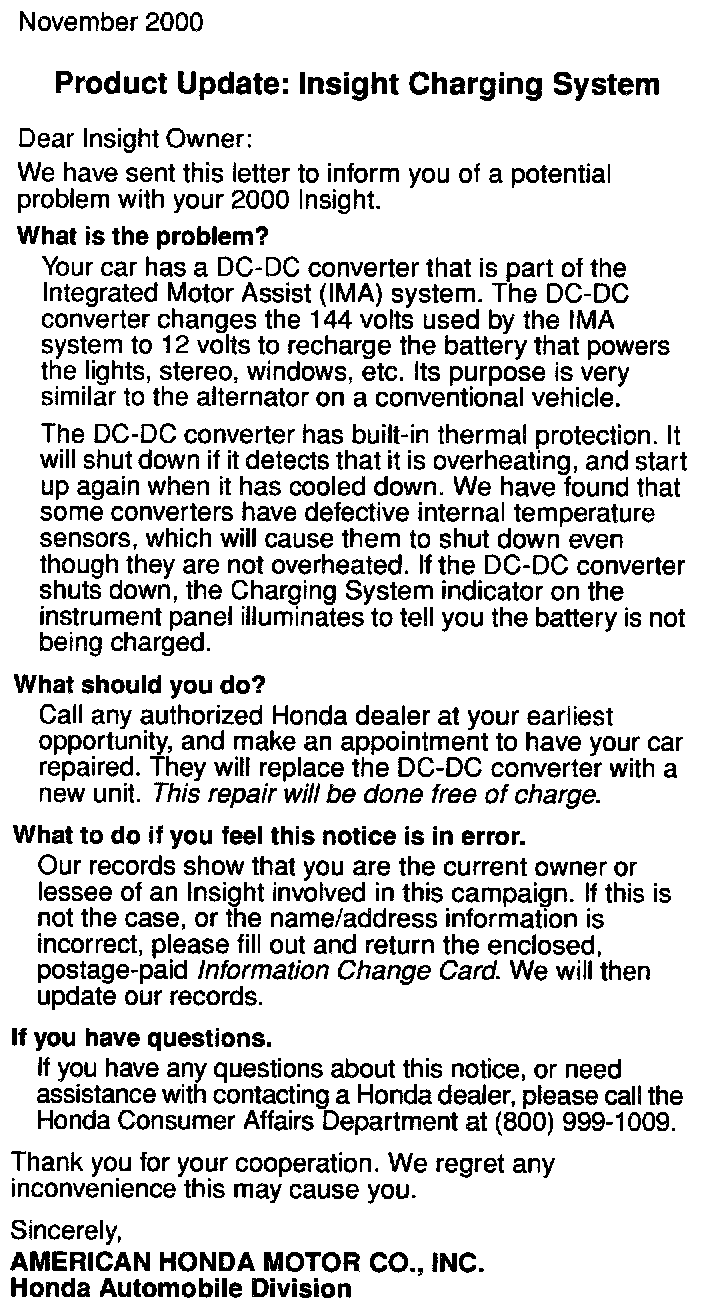
All owners of affected vehicles will be sent a notification of this product update. An example of the customer notification is shown.
CORRECTIVE ACTION
Replace the DC-DC converter.
PARTS INFORMATION
DC-DC Converter: P/N 1C800-PHM-003, H/C 6339857
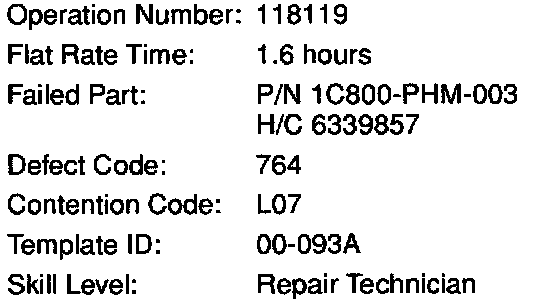
WARRANTY CLAIM INFORMATION
REPAIR PROCEDURE
1. Disconnect the negative cable from the under-hood 12V battery.
2. Remove the cargo area floor carpet.
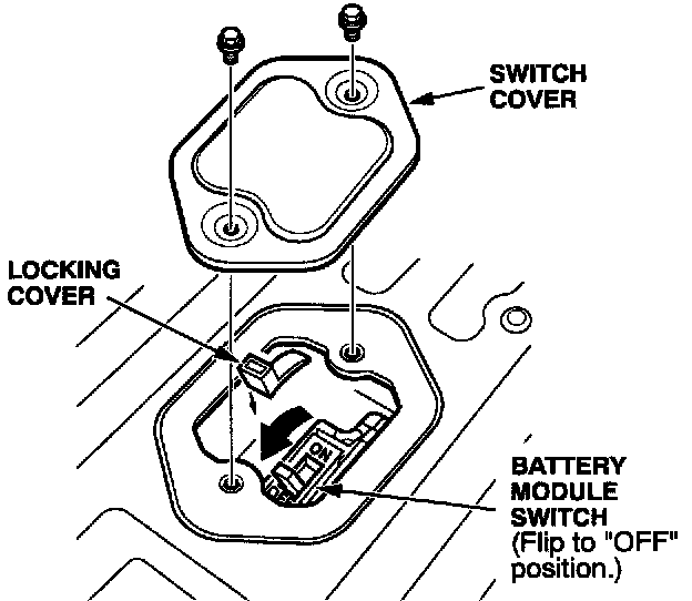
3. Remove the battery module switch cover. Remove the locking cover, turn off the battery module switch, then reinstall the locking cover.
4. Wait for at least 5 minutes for the capacitors in the system to discharge.
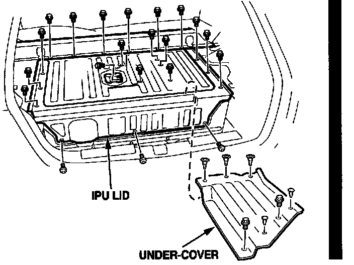
*5. Remove the under-cover and the IPU lid.*
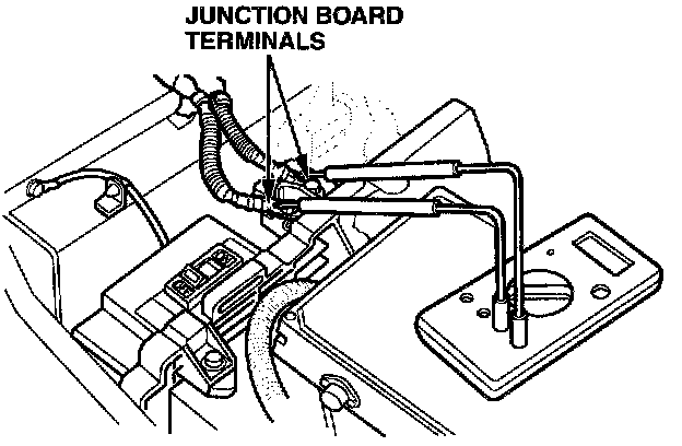
*6. Measure the voltage between the junction board terminals. There should be 10V or less.
^ If there is more than 10V, there is a problem in the IMA system. Look for and troubleshoot any DTCs before continuing.
^ If there is 10V or less, continue to step 7.*
7. Remove the foam inserts.
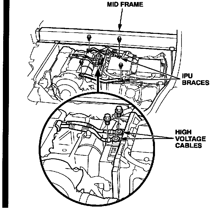
*8. Remove the IPU braces. Disconnect the high voltage cables from the junction board.*
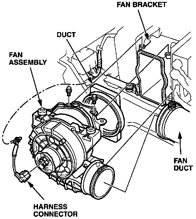
9. Disconnect the harness connector and harness clip from the cooling fan assembly.
10. Remove the fan mounting bolts, the fan bracket, and the fan duct from the fan assembly. Remove the fan assembly.
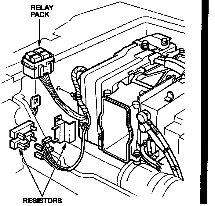
*11. Remove the relay pack from its holder. Disconnect the harness ends from the resistors, and disconnect the harness clips from the body.*
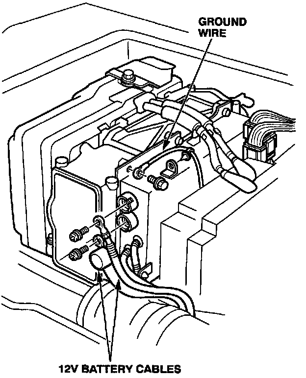
12. Disconnect the ground wire. Disconnect the 12V battery cables.
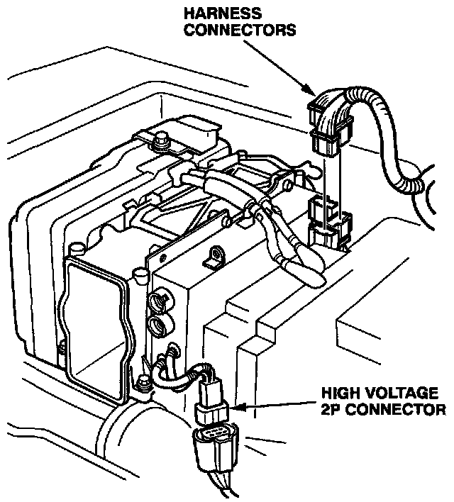
13. Disconnect the harness connectors from the PCU. Disconnect the high voltage 2P connector.
14. Pull the air intake duct away from the front of the PCU.
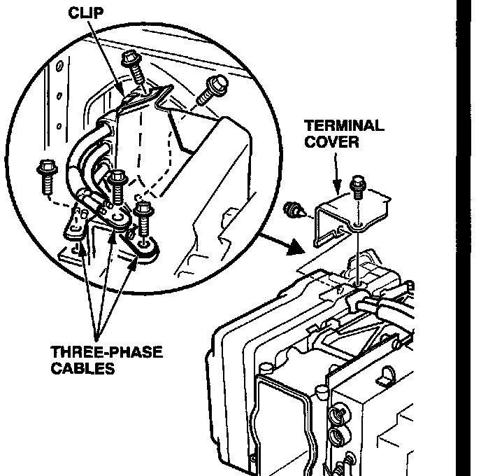
15. Remove the terminal cover. Disconnect the three-phase cables from the PCU (three bolts and one clip).
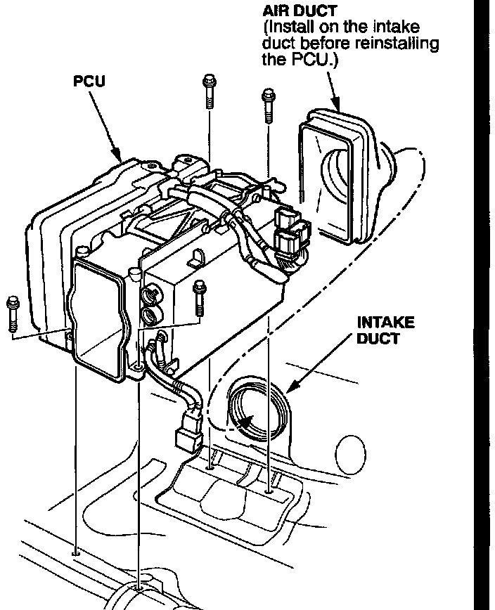
16. Remove the PCU mounting bolts. Carefully lift the PCU out of the vehicle.
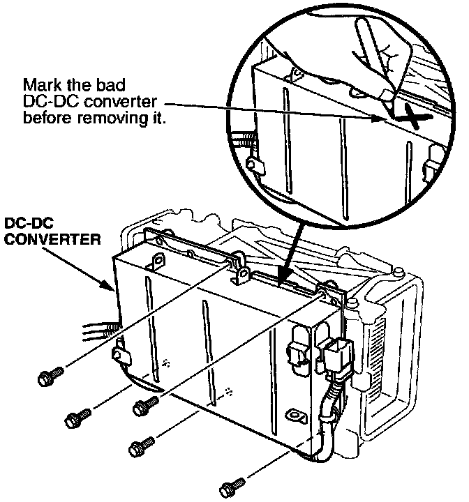
17. Remove the DC-DC converter mounting bolts. Remove the converter from the PCU.
18. Install the new DC-DC converter.
19. Remove the air intake from the side of the PCU and reinstall it on the air duct in the vehicle.
20. Install the PCU into the vehicle in the reverse order of removal. Make sure the air intake duct is aligned properly with the PCU.
21. Reinstall the remaining parts. Make sure you turn on the battery module switch.
22. Reconnect the negative cable to the 12V battery.
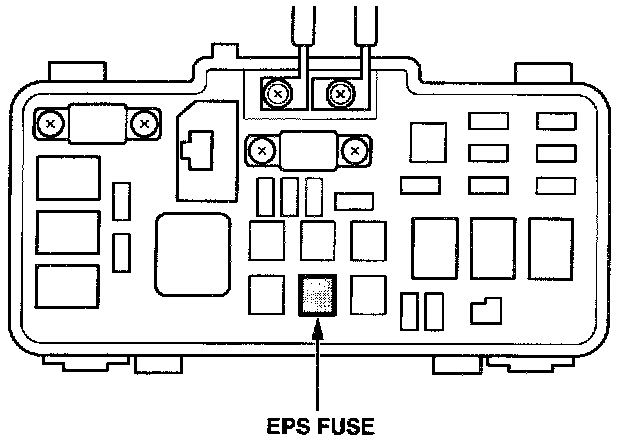
23. Remove the EPS fuse from the under-hood fusel relay box.
24. Turn the ignition switch ON (II). Make sure the charging system indicator illuminates. Then start the engine, and make sure the charging system indicator goes off.
25. With the transmission in neutral and the clutch released, run the engine at 3,500 rpm until the battery level gauge shows at least 50 percent charge.
26. Turn off the engine. Reinstall the EPS fuse.

27. Center-punch a completion mark above the last character of the engine compartment VIN.

Disclaimer