 |
absggw00001300
ENGINE REMOVAL/INSTALLATION [WL-3]
id0110b5800400
1. Remove the air intake pipe. (See INTAKE-AIR SYSTEM REMOVAL/INSTALLATION [WL-3].)
2. Remove the battery. (See BATTERY REMOVAL/INSTALLATION [WLT-1, WLT-2, WL-3, WL-C, WE-C].)
3. Remove the radiator. (See GENERATOR REMOVAL/INSTALLATION [WLT-1, WLT-2, WL-3, WL-C, WE-C].)
4. Remove the front pipe. (See EXHAUST SYSTEM REMOVAL/INSTALLATION [WL-3].)
5. Remove the transmission. (See TRANSMISSION REMOVAL/INSTALLATION [R15M-D].)
6. Remove the P/S oil pump with the oil hoses and pipes still connected. (See POWER STEERING OIL PUMP REMOVAL/INSTALLATION [WLT-1, WLT-2, WL-3, WL-C, WE-C].)
7. Remove the A/C compressor with the pipes still connected. (See A/C COMPRESSOR REMOVAL/INSTALLATION.)
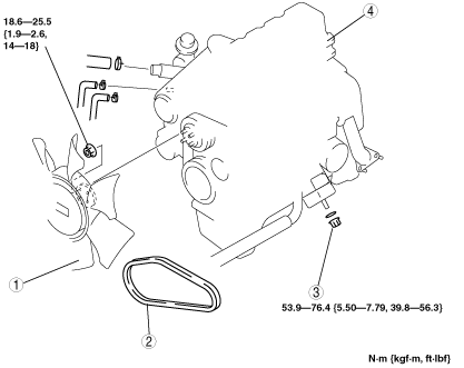
8. Remove the order indicated in the table.
9. Install in the reverse order of removal.
10. Adjust the drive belt deflection. (See DRIVE BELT ADJUSTMENT [WL-3].)
11. Bleed air in the fuel line. (See AFTER REPAIR PROCEDURE [WL-3].)
12. Start the engine and
13. Perform a road test.
absggw00001300
|
|
1
|
Cooling fan
|
|
2
|
Drive belt
|
|
3
|
Engine mount nut
|
|
4
|
Engine
|
Engine Removal/Installation Note
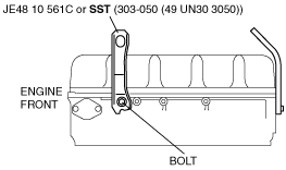
1. Install the engine hanger (JE48 10 561C) or SST (303-050 (49 UN30 3050)) to the cylinder head using bolt (99794 0820 or M8X1.25, 6T, length 20mm {0.79 in}) as shown.
absggw00001301
|
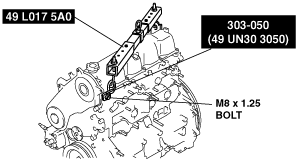
2. If the SST (303-050 (49 UN30 3050)) is used, use the SST (49 L017 5A0) when suspending the engine.
3. Install the SST to the cylinder head using the bolt (99794 0820 or M8X1.25, 6T, length 20mm {0.79 in}) as shown in the figure.
absggw00001302
|