 |
arnffw00000575
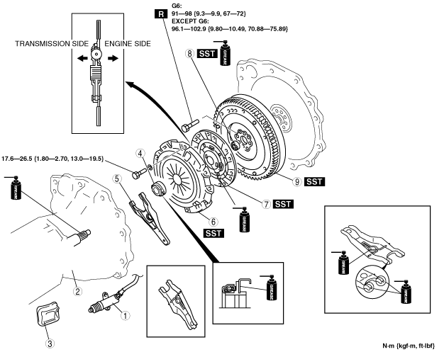
CLUTCH UNIT REMOVAL/INSTALLATION [M15M-D, R15M-D, R15MX-D]
id0510008003a8
1. Remove in the order indicated in the table.
2. Install in the reverse order of removal.
arnffw00000575
|
|
1
|
Clutch release cylinder
|
|
2
|
Manual transmission
|
|
3
|
Boot
|
|
4
|
Clutch release collar
|
|
5
|
Clutch release fork
|
|
6
|
Clutch cover
|
|
7
|
Clutch disc
|
|
8
|
Pilot bearing
(See Pilot Bearing Removal Note.)
|
|
9
|
Flywheel
(See Flywheel Removal Note [G6].)
|
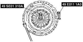
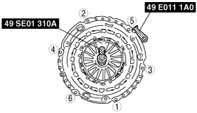
Clutch Cover and Disc Removal Note
1. Install the SSTs.
2. Loosen each bolt one turn at a time in a crisscross pattern until spring tension is released.
3. Remove the clutch cover and disc.
arnffw00000564
|
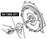
Pilot Bearing Removal Note
1. Use the SST to remove the pilot bearing.
arnffw00000576
|
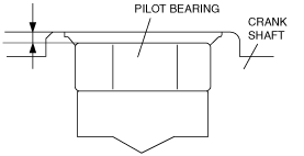
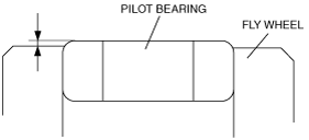
Pilot Bearing Installation Note
1. Use the SSTs to install the pilot bearing.
absggw00001237
|
G6
arnffw00000577
|
WLT-1, WLT-2, WL-3
arnffw00000578
|
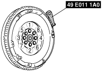
Flywheel Removal Note [G6]
1. Lock the flywheel against rotation using the SST.
2. Loosen the lock bolts uniformly and gradually in the order shown in the figure, and remove them.
3. Remove the flywheel.
arnffw00000573
|
4. Remove the SST.
5. Inspect for oil leakage from the crankshaft rear oil seal.
Flywheel Removal Note [Except G6]
1. Lock the flywheel against rotation using the SST.
2. Loosen the lock bolts uniformly and gradually in the order shown in the figure, and remove them.
3. Remove the flywheel.
arnffw00000568
|
4. Remove the SST.
5. Inspect for oil leakage from the crankshaft rear oil seal.
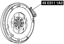
Flywheel Installation Note [G6]
1. Clean the crankshaft thread holes.
2. Install the flywheel to the crankshaft.
3. Temporarily tighten the new lock bolts.
4. Lock the flywheel against rotation using the SST.
arnffw00000570
|
5. Tighten the lock bolts uniformly and gradually in the order shown in the figure.
6. Remove the SST.
Flywheel Installation Note [Except G6]
1. Clean the crankshaft thread holes.
2. Install the flywheel to the crankshaft.
3. Temporarily tighten the new lock bolts.
4. Lock the flywheel against rotation using the SST.
arnffw00000569
|
5. Tighten the lock bolts uniformly and gradually in the order shown in the figure.
6. Remove the SST.
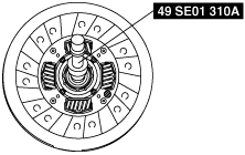
Clutch Disc Installation Note
1. Hold the clutch disc position using the SST.
arnffw00000571
|
Clutch Cover Installation Note
1. Install the SSTs.
2. Tighten the bolts evenly and gradually in a crisscross pattern.
arnffw00000572
|