1. SRS system check
Refer to "58.SRS Control 8A.Troubleshooting(Air Bag (Driver/Passenger)) diagnostic system check-SRS controls".
2. Driver airbag circuit resistance check
1) Observe the Driver Airbag Loop Resistance parameter on the scan tool. Is the Driver Airbag Loop Resistance parameter more than or equal to the specified value?
Value: 7 Ω
Yes
=>Go to SRS coil harness connector connection verification.
No
Go to Intermittent conditions of SRS control.
Refer to "209.Restraints 22D.Symptom Intermittent conditions of SRS control".
3. SRS coil harness connector connection verification
1) Turn OFF the ignition switch for 15 seconds or more.
2) Verify that the SRS coil harness connector (B35) on the lower part of the combination switch is securely connected. Is the SRS coil harness connector (B35) securely connected?
Refer to "LHD SRS airbag (Driver/Passenger)" in the ETM (wiring diagram). (Open using the ETM viewer.).
Refer to "RHD SRS airbag (Driver/Passenger)" in the ETM (wiring diagram). (Open using the ETM viewer.).
Yes
=>Go to SRS coil harness connector inspection.
No
Securely connect the SRS coil harness connector (B35).
4. SRS coil harness connector inspection
1) Disconnect the SRS coil harness connector (B35) on the lower part of the combination switch.
2) Inspect the SRS coil harness connector terminals (pins 1 and 2 of B35) for bending, dirt, etc. Is the result normal?
Refer to "LHD SRS airbag (Driver/Passenger)" in the ETM (wiring diagram). (Open using the ETM viewer.).
Refer to "RHD SRS airbag (Driver/Passenger)" in the ETM (wiring diagram). (Open using the ETM viewer.).
Yes
No
Repair the connections as necessary.
5. Current DTC check
1) Connect the SRS coil harness connector (B35) on the lower part of the combination switch.
Refer to "LHD SRS airbag (Driver/Passenger)" in the ETM (wiring diagram). (Open using the ETM viewer.).
Refer to "RHD SRS airbag (Driver/Passenger)" in the ETM (wiring diagram). (Open using the ETM viewer.).
2) Turn ON the ignition switch.
3) Observe the DTC information with a scan tool for DTC B0001[1B] being set as a current failure. Is a DTC set?
Yes
=>Go to Driver airbag circuit check.
No
6. Driver airbag circuit check
1) Turn OFF the ignition switch for 15 seconds or more.
2) Disconnect the SRS coil harness connector (B35) on the lower part of the combination switch.
3) Connect the SRS alternative load and the SRS adapter for load tool to the SRS coil harness connector (B35) on the SRS control unit side.
Refer to "LHD SRS airbag (Driver/Passenger)" in the ETM (wiring diagram). (Open using the ETM viewer.).
Refer to "RHD SRS airbag (Driver/Passenger)" in the ETM (wiring diagram). (Open using the ETM viewer.).
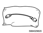
SST: 5-8840-2982-0 - SRS adapter for load tool
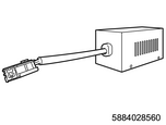
SST: 5-8840-2856-0 - SRS alternative load
4) Turn ON the ignition switch.
5) Observe the DTC information with a scan tool for DTC B0001[1B] being set as a current failure. Is a DTC set?
Yes
=>Go to Inspection for open circuit in driver airbag deployment current output (High) circuit.
No
7. Inspection for open circuit in driver airbag deployment current output (High) circuit
1) Turn OFF the ignition switch for 15 seconds or more.
2) Inspect the driver airbag deployment current output (High) circuit between the SRS control unit (pin 23 of B8) and the SRS coil (pin 1 of B35) for an open circuit or high resistance. Is the result normal?
Refer to "LHD SRS airbag (Driver/Passenger)" in the ETM (wiring diagram). (Open using the ETM viewer.).
Refer to "RHD SRS airbag (Driver/Passenger)" in the ETM (wiring diagram). (Open using the ETM viewer.).
Yes
=>Go to Inspection for open circuit in driver airbag deployment current output (Low) circuit.
No
Repair the circuit as necessary.
8. Inspection for open circuit in driver airbag deployment current output (Low) circuit
1) Inspect the driver airbag deployment current output (Low) circuit between the SRS control unit (pin 24 of B8) and the SRS coil (pin 2 of B35) for an open circuit or high resistance. Is the result normal?
Refer to "LHD SRS airbag (Driver/Passenger)" in the ETM (wiring diagram). (Open using the ETM viewer.).
Refer to "RHD SRS airbag (Driver/Passenger)" in the ETM (wiring diagram). (Open using the ETM viewer.).
Yes
=>Go to SRS control unit harness connector inspection.
No
Repair the circuit as necessary.
9. SRS control unit harness connector inspection
1) Inspect for poor connections at the SRS control unit harness connector (pins 23 and 24 of B8). Is the result normal?
Refer to "LHD SRS airbag (Driver/Passenger)" in the ETM (wiring diagram). (Open using the ETM viewer.).
Refer to "RHD SRS airbag (Driver/Passenger)" in the ETM (wiring diagram). (Open using the ETM viewer.).
Yes
=>Go to SRS control unit replacement.
No
Repair the connections as necessary.
10. SRS coil check
1) Turn OFF the ignition switch for 15 seconds or more.
2) Remove the SRS alternative load and the adapter.
3) Remove the driver airbag.
Refer to "8.Restraints 8B.Airbag Systems driver airbag removal".
4) Connect the SRS alternative load and the appropriate adapter from the adapter harness kit to the driver airbag harness connector.
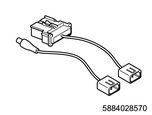
SST: 5-8840-2857-0 - adapter harness kit
SST: 5-8840-2856-0 - SRS alternative load
5) Connect the SRS coil harness connector (B35) on the lower part of the combination switch.
Refer to "LHD SRS airbag (Driver/Passenger)" in the ETM (wiring diagram). (Open using the ETM viewer.).
Refer to "RHD SRS airbag (Driver/Passenger)" in the ETM (wiring diagram). (Open using the ETM viewer.).
6) Turn ON the ignition switch.
7) Observe the DTC information with a scan tool for DTC B0001[1B] being set as a current failure. Is a DTC set?
Yes
Replace the combination switch.
Refer to "9.Body, Cab, Accessories 9A.Lighting Systems combination switch removal".
Refer to "9.Body, Cab, Accessories 9A.Lighting Systems combination switch installation".
No
Replace the driver airbag.
Refer to "8.Restraints 8B.Airbag Systems driver airbag removal".
Refer to "8.Restraints 8B.Airbag Systems driver airbag installation".
11. SRS control unit replacement
Note
- Perform the VIN programming and ECU lock after replacing the SRS control unit.
Refer to "8.Restraints 8Z.Seat Belt and SRS Airbag Electrical Control SRS control unit removal".
Refer to "8.Restraints 8Z.Seat Belt and SRS Airbag Electrical Control SRS control unit installation".
Refer to "8.Restraints 8Z.Seat Belt and SRS Airbag Electrical Control SRS control unit setting".
Procedure completion
12. Repair verification
1) Reconnect all of the disconnected harness connectors.
2) Clear the DTC with a scan tool.
3) Turn OFF the ignition switch for 15 seconds or more.
4) Turn ON the ignition switch.
5) Observe the DTC information with a scan tool.