 |
ac5wzw00001928
CLIMATE CONTROL UNIT REMOVAL/INSTALLATION [MANUAL AIR CONDITIONER]
id0740a2807400
L.H.D.
Removal
1. Disconnect the negative battery cable. (See NEGATIVE BATTERY CABLE DISCONNECTION/CONNECTION [SKYACTIV-G 2.0, SKYACTIV-G 2.5].)(See NEGATIVE BATTERY CABLE DISCONNECTION/CONNECTION [SKYACTIV-G 2.0, SKYACTIV-G 2.5 (WITHOUT i-stop)].)(See NEGATIVE BATTERY CABLE DISCONNECTION/CONNECTION [SKYACTIV-D 2.2].)
2. Remove the following parts:
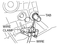
3. Press the tab down, then slide the wire off the link.
ac5wzw00001928
|
4. Remove the wire from the wire clamp.
5. Remove in the order indicated in the table.
ac5wzw00001929
|
|
1
|
Screw
|
|
2
|
Connector
|
|
3
|
Climate control unit
|
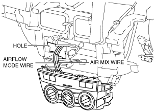
6. Pull out the air mix wire and airflow mode wire from the dashboard.
ac5wzw00001930
|
Install
1. Pass each wire through the hole on the dashboard as shown in the figure.
ac5wzw00001930
|
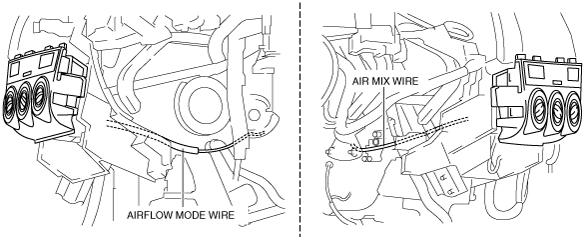
2. Route each wire as shown in the figure.
ac5wzw00001931
|
3. Install in the order indicated in the table.
ac5wzw00001932
|
|
1
|
Connector
|
|
2
|
Climate control unit
|
|
3
|
Screw
|
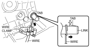
4. Connect each wire to links and install it to the wire clamps.
ac5wzw00001933
|
5. Verify that the dial operation is correct by fully turning each of the dials from one end to the other.
6. Install the following parts:
7. Connect the negative battery cable. (See NEGATIVE BATTERY CABLE DISCONNECTION/CONNECTION [SKYACTIV-G 2.0, SKYACTIV-G 2.5].)(See NEGATIVE BATTERY CABLE DISCONNECTION/CONNECTION [SKYACTIV-G 2.0, SKYACTIV-G 2.5 (WITHOUT i-stop)].)(See NEGATIVE BATTERY CABLE DISCONNECTION/CONNECTION [SKYACTIV-D 2.2].)
R.H.D.
Removal
1. Disconnect the negative battery cable. (See NEGATIVE BATTERY CABLE DISCONNECTION/CONNECTION [SKYACTIV-G 2.0, SKYACTIV-G 2.5].)(See NEGATIVE BATTERY CABLE DISCONNECTION/CONNECTION [SKYACTIV-G 2.0, SKYACTIV-G 2.5 (WITHOUT i-stop)].)(See NEGATIVE BATTERY CABLE DISCONNECTION/CONNECTION [SKYACTIV-D 2.2].)
2. Remove the following parts:
3. Press the tab down, then slide the wire off the link.
ac5wzw00001928
|
4. Remove the wire from the wire clamp.
5. Remove in the order indicated in the table.
ac5wzw00001929
|
|
1
|
Screw
|
|
2
|
Connector
|
|
3
|
Climate control unit
|
6. Pull out the air mix wire and airflow mode wire from the dashboard.
ac5wzw00001934
|
Install
1. Pass each wire through the hole on the dashboard as shown in the figure.
ac5wzw00001934
|
2. Route each wire as shown in the figure.
ac5wzw00001935
|
3. Install in the order indicated in the table.
ac5wzw00001932
|
|
1
|
Connector
|
|
2
|
Climate control unit
|
|
3
|
Screw
|
4. Connect each wire to links and install it to the wire clamps.
ac5wzw00001933
|
5. Verify that the dial operation is correct by fully turning each of the dials from one end to the other.
6. Install the following parts:
7. Connect the negative battery cable. (See NEGATIVE BATTERY CABLE DISCONNECTION/CONNECTION [SKYACTIV-G 2.0, SKYACTIV-G 2.5].)(See NEGATIVE BATTERY CABLE DISCONNECTION/CONNECTION [SKYACTIV-G 2.0, SKYACTIV-G 2.5 (WITHOUT i-stop)].)(See NEGATIVE BATTERY CABLE DISCONNECTION/CONNECTION [SKYACTIV-D 2.2].)