|
ac5wzw00006718
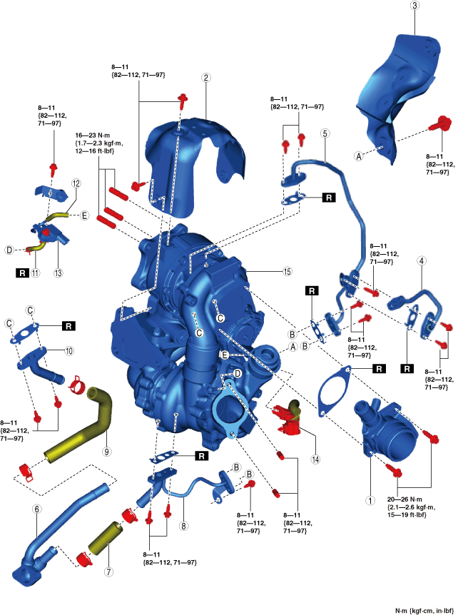
TURBOCHARGER REMOVAL/INSTALLATION [SKYACTIV-D 2.2]
id0113z7705800
Fuel injector (2pin type)
|
Washer
Quantity: 4
Location of use: Water pipe No.1
|
Gasket
Quantity: 1
Location of use: Water pipe No.1
|
Washer
Quantity: 4
Location of use: Oil pipe No.4
|
|
Gasket
Quantity: 2
Location of use: Water pipe No.3
|
Nut
Quantity: 4
Location of use: Turbocharger
|
Gasket
Quantity: 1
Location of use: Turbocharger
|
|
Washer
Quantity: 2
Location of use: Water pipe No.2
|
Gasket
Quantity: 1
Location of use: Water pipe No.2
|
Gasket
Quantity: 2
Location of use: Oil pipe No.2
|
|
Gasket
Quantity: 1
Location of use: Oil pipe No.3
|
Washer
Quantity: 4
Location of use: Oil pipe No.1
|
Vacuum hose
Quantity: 1
Location of use: MAP sensor No.1
|
Fuel injector (6pin type)
|
Stud
Quantity: 3
Location of use: Turbocharger
|
Gasket
Quantity: 1
Location of use: Oil pipe No.3
|
Gasket
Quantity: 1
Location of use: Oil pipe No.4
|
|
Gasket
Quantity: 1
Location of use: Turbocharger air inlet pipe
|
Nut
Quantity: 3
Location of use: Turbocharger
|
Gasket
Quantity: 1
Location of use: Turbocharger
|
|
Gasket
Quantity: 1
Location of use: Oil pipe No.5
|
Gasket
Quantity: 2
Location of use: Oil pipe No.1
|
Gasket
Quantity: 2
Location of use: Oil pipe No.2
|
|
Vacuum hose No.1
Quantity: 1
Location of use: MAP sensor No.1
|
—
|
—
|
Operation After Replacing or Removal/Installation Turbocharger
1. If the turbocharger is replaced or removed/installed, perform the following procedure.
Fuel injector (2pin type)
|
STEP |
ACTION |
PAGE/CONDITION |
|---|---|---|
|
1
|
Perform turbocharger initialization procedure.
|
|
|
2
|
Switch the ignition off.
|
—
|
|
3
|
Wait for 20 s.
|
—
|
|
4
|
Switch the ignition ON (engine off).
|
—
|
|
5
|
Perform KOEO self-test procedure.
|
|
|
6
|
Perform KOER self-test procedure.
|
Fuel injector (6pin type)
|
STEP |
ACTION |
PAGE/CONDITION |
|---|---|---|
|
1
|
Switch the ignition ON (engine off).
|
—
|
|
2
|
Perform KOEO self-test procedure.
|
|
|
3
|
Perform KOER self-test procedure.
|
Turbocharger Removal/Installation (Fuel injector (2pin type))
1. Disconnect the negative battery terminal. (See NEGATIVE BATTERY TERMINAL DISCONNECTION/CONNECTION.)
2. Remove the engine cover. (See ENGINE COVER REMOVAL/INSTALLATION [SKYACTIV-D 2.2].)
3. Drain the engine coolant. (See ENGINE COOLANT REPLACEMENT [SKYACTIV-D 2.2].)
4. Remove the air cleaner. (See INTAKE-AIR SYSTEM REMOVAL/INSTALLATION [SKYACTIV-D 2.2].)
5. Remove the battery and the battery tray. (See BATTERY REMOVAL/INSTALLATION [SKYACTIV-D 2.2].)
6. Remove the following parts as a single unit: (See INTAKE-AIR SYSTEM REMOVAL/INSTALLATION [SKYACTIV-D 2.2].)
7. Set the turbocharger air outlet pipe component aside as a single unit as shown in the figure. (See INTAKE-AIR SYSTEM REMOVAL/INSTALLATION [SKYACTIV-D 2.2].)
ac5wzw00006718
|
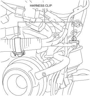
8. Remove the wiring harness clip shown in the figure.
ac5wzw00005704
|
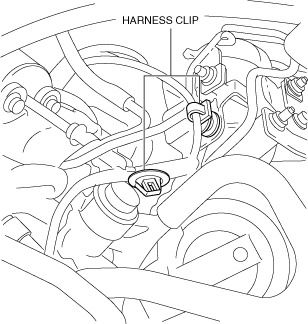
9. Disconnect the regulating valve position sensor connector.
10. Detach the wiring harness clips shown in the figure.
ac5wzw00005705
|
11. Remove the front crossmember. (See FRONT CROSSMEMBER REMOVAL/INSTALLATION.)
12. Remove the catalytic converter. (See EXHAUST SYSTEM REMOVAL/INSTALLATION [SKYACTIV-D 2.2].)
13. Remove the transfer. (4WD)(See TRANSFER REMOVAL/INSTALLATION [GW6AX-EL (SKYACTIV-D 2.2)].)
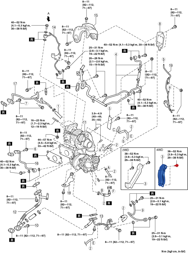
14. Remove in the order shown in the figure.
15. Install in the reverse order of removal.
16. Refill the engine coolant. (See ENGINE COOLANT REPLACEMENT [SKYACTIV-D 2.2].)
17. Perform the following procedure.
ac5wzw00014358
|
|
1
|
Water hose
|
|
2
|
Vacuum hose
|
|
3
|
Turbocharger bracket
|
|
4
|
Water pipe No.1
|
|
5
|
Turbocharger insulator No.1
|
|
6
|
Water pipe No.2 installation bolt
|
|
7
|
Water pipe No.3 installation bolt
|
|
8
|
Turbocharger insulator No.2
|
|
9
|
Oil pipe No.1
|
|
10
|
Oil pipe No.2 installation bolt
|
|
11
|
Turbocharger
|
|
12
|
Oil pipe No.2
(See Oil pipe No.2 removal note.)
|
|
13
|
Oil pipe No.3
|
|
14
|
Oil pipe No.4
|
|
15
|
Turbocharger insulator No.3
|
|
16
|
Water pipe No.2
|
|
17
|
Water pipe No.3
|
|
18
|
Turbocharger insulator No.4
|
Oil pipe No.2 removal note
1. Remove oil pipes No.2 and 3 as a single unit.
2. Remove oil pump No.2.
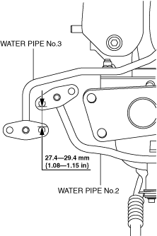
Water pipe No.2 installation note
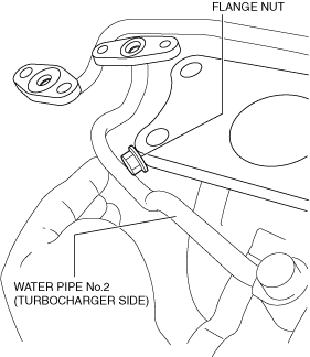
1. Insert a flange nut (M10 (Approx. 9 mm {0.4 in})) between the position shown in the figure and tighten water pipe No.2 (turbocharger side).
ac5wzw00008621
|
2. Measure the distance shown in the figure and verify that water pipe No.2 is installed correctly.
ac5wzw00008622
|
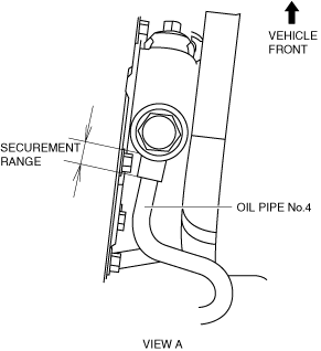
Oil pipe No.4 installation note
1. Secure oil pipe No.4 using a wrench so that it does not rotate.
ac5wzw00008623
|
2. Tighten the oil pipe No.4.
Oil pipe No.2 installation note
1. Install the oil pipe No.2 as shown in the figure.
ac5wzw00006723
|
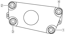
Turbocharger installation note
1. Install the turbocharger using the following procedure.
ac5wzw00005703
|
ac5wzw00005745
|
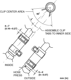
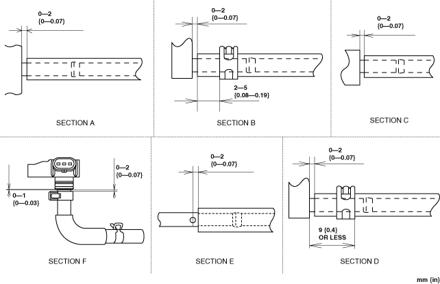
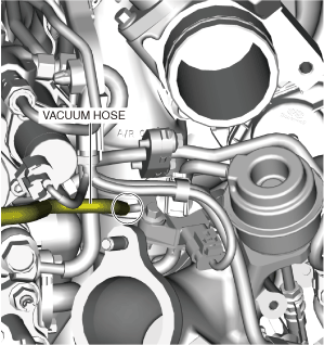
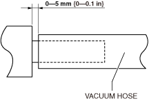
Vacuum hose installation note
1. Install the vacuum hose as shown in the figure.
ac5wzw00006722
|
Turbocharger Removal/Installation (Fuel injector (6pin type))
1. Disconnect the negative battery terminal. (See NEGATIVE BATTERY TERMINAL DISCONNECTION/CONNECTION.)
2. Remove the engine cover. (See ENGINE COVER REMOVAL/INSTALLATION [SKYACTIV-D 2.2].)
3. Drain the engine coolant. (See ENGINE COOLANT REPLACEMENT [SKYACTIV-D 2.2].)
4. Remove the air cleaner. (See INTAKE-AIR SYSTEM REMOVAL/INSTALLATION [SKYACTIV-D 2.2].)
5. Remove the battery and the battery tray. (See BATTERY REMOVAL/INSTALLATION [SKYACTIV-D 2.2].)
6. Remove the following parts as a single unit: (See INTAKE-AIR SYSTEM REMOVAL/INSTALLATION [SKYACTIV-D 2.2].)
7. Remove the nuts and set the turbocharger air outlet pipe component aside. (See INTAKE-AIR SYSTEM REMOVAL/INSTALLATION [SKYACTIV-D 2.2].)
ac5wzw00012021
|
8. Disconnect the blow-by heater connector. (See INTAKE-AIR SYSTEM REMOVAL/INSTALLATION [SKYACTIV-D 2.2].)
9. Disconnect the breather hose from the blow-by heater side. (See INTAKE-AIR SYSTEM REMOVAL/INSTALLATION [SKYACTIV-D 2.2].)
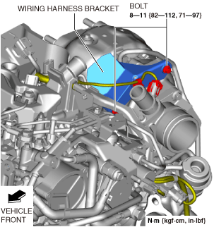
10. Remove the bolts shown in the figure and set aside the wiring harness bracket and wiring harness as a single unit.
ac5wzw00012022
|
11. Disconnect the MAP sensor No.1 connector. (See MANIFOLD ABSOLUTE PRESSURE (MAP) SENSOR REMOVAL/INSTALLATION [SKYACTIV-D 2.2].)
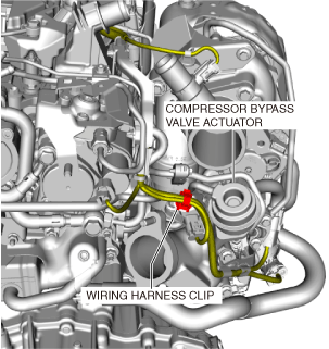
12. Disconnect the wiring harness clips shown in the figure.
ac5wzw00012023
|
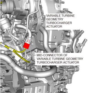
13. Disconnect the variable turbine geometry turbocharger actuator mid-connector.
ac8wzw00002658
|
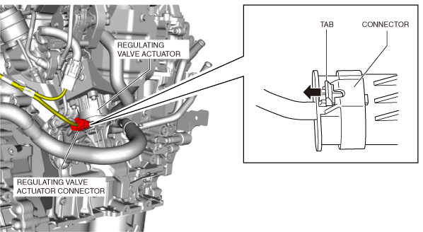
14. Disconnect the regulating valve actuator connector using the following procedure.
ac5wzw00012025
|
15. Remove the bolts shown in the figure and set aside the wiring harness bracket and wiring harness as a single unit.
ac5wzw00012026
|
16. Disconnect the vacuum hose as shown in the figure.
ac5wzw00012027
|
17. Remove the front crossmember. (See FRONT CROSSMEMBER REMOVAL/INSTALLATION.)
18. Remove the catalytic converter. (See EXHAUST SYSTEM REMOVAL/INSTALLATION [SKYACTIV-D 2.2].)
19. Remove the transfer. (4WD)(See TRANSFER REMOVAL/INSTALLATION [GW6AX-EL (SKYACTIV-D 2.2)].)
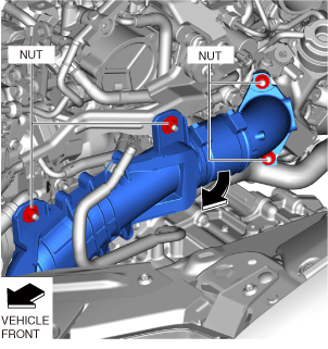
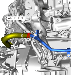
20. Disconnect the water hose as shown in the figure.
ac5wzw00012028
|
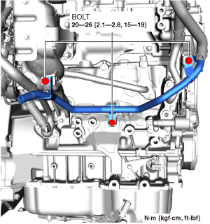
21. Remove the bolts shown in the figure and set aside the water pipe.
ac5wzw00012029
|
22. Remove in the order shown in the figure.
23. Install in the reverse order of removal.
24. Refill the engine coolant. (See ENGINE COOLANT REPLACEMENT [SKYACTIV-D 2.2].)
25. Perform the following procedure.
Step 1
ac5wzw00012030
|
|
1
|
Turbocharger bracket
|
|
2
|
Turbocharger insulator No.1
|
|
3
|
Turbocharger component
|
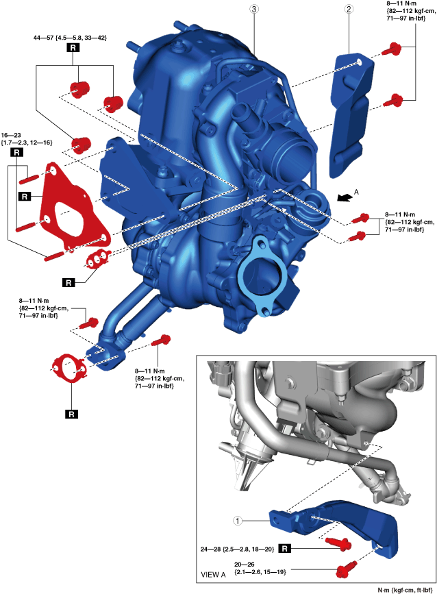
Step 2
ac5wzw00014359
|
|
1
|
Turbocharger air inlet pipe
|
|
2
|
Turbocharger insulator No.2
|
|
3
|
Turbocharger insulator No.3
|
|
4
|
Oil pipe No.1
|
|
5
|
Oil pipe No.2
|
|
6
|
Oil pipe No.3
|
|
7
|
Oil hose No.1
|
|
8
|
Oil pipe No.4
|
|
9
|
Oil hose No.2
|
|
10
|
Oil pipe No.5
|
|
11
|
Vacuum hose No.1
|
|
12
|
Vacuum hose No.2
|
|
13
|
MAP sensor No.1
|
|
14
|
Variable turbine geometry turbocharger actuator connector
|
|
15
|
Turbocharger
|
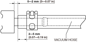
Vacuum hose No.2 installation note
1. Install the vacuum hose No.2 as shown in the figure.
ac5wzw00012032
|
Vacuum hose No.1 installation note
1. Install the vacuum hose No.1 as shown in the figure.
ac5wzw00012033
|
Oil hose No.2 installation note
1. Install the oil hose No.2 as shown in the figure.
ac5wzw00012034
|
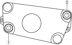
Oil pipe No.4 installation note
1. Temporarily tighten bolts (1), and (2) shown in the figure.
ac5wzw00012035
|
2. Tighten bolt (1).
3. Tighten bolt (2).
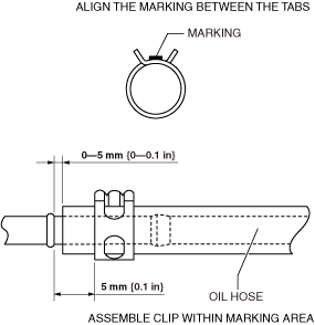
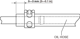
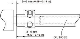
Oil hose No.1 installation note
1. Install the Oil hose No.1 as shown in the figure.
Oil pipe No.4 side
ac5wzw00012036
|
Oil pipe No.3 side
ac5wzw00012037
|
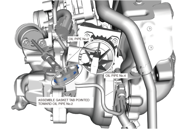
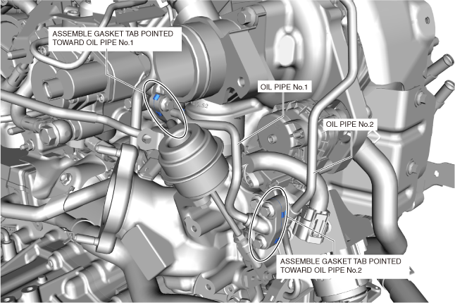
Oil pipe No.2 installation note
1. Install the gasket as shown in the figure.
ac5wzw00012038
|
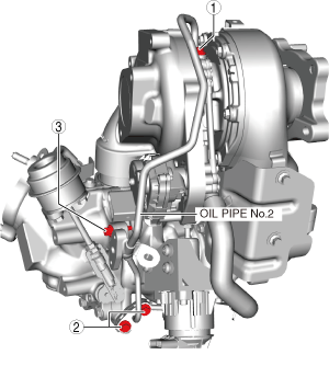
2. Temporarily tighten bolts (1), (2), and (3) shown in the figure.
ac5wzw00012039
|
3. Tighten bolts (1) and (2).
4. Tighten bolt (3).
Oil pipe No.1 installation note
1. Install the gaskets as shown in the figure.
ac5wzw00012040
|
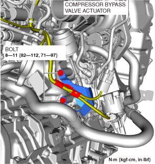
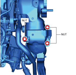
Turbocharger component installation note
1. Install the new stud bolts to the exhaust manifold.
2. Tighten the nuts shown in the figure to the specified torque.
ac5wzw00012041
|
3. Tighten the nut to the specified torque again.