 |
ac5uuw00005828
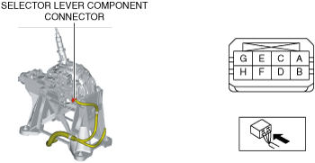
SHIFT-LOCK SOLENOID INSPECTION
id051800298100
1. Disconnect the negative battery terminal. (See NEGATIVE BATTERY TERMINAL DISCONNECTION/CONNECTION.)
2. Remove the following parts:
3. Reconnect the negative battery terminal. (See NEGATIVE BATTERY TERMINAL DISCONNECTION/CONNECTION.)
4. Verify that the voltages of each of the selector lever component terminals are as indicated in the table.
ac5uuw00005828
|
Shift-lock solenoid specification
|
Terminal |
Connected to |
Test condition |
Voltage (V) |
|
|---|---|---|---|---|
|
A
|
IG1 relay
|
Ignition switched ON (engine on)
|
B+
|
|
|
Except above
|
Below 1.0
|
|||
|
D
|
Start stop unit
|
Ignition switched ON
|
All of the following conditions are met.
• Selector lever is in P position
• Brake pedal is depressed (brake light switch is on)
|
Below 1.0
|
|
Except above
|
B+
|
|||