 |
ac5uuw00003554
EPS CONTROL MODULE INSPECTION
id061300802400
1. Remove the driver-side front scuff plate. (See FRONT SCUFF PLATE REMOVAL/INSTALLATION.)
2. Remove the driver-side front side trim. (See FRONT SIDE TRIM REMOVAL/INSTALLATION.)
3. Remove the lower decoration panel. (See DECORATION PANEL REMOVAL/INSTALLATION.)
4. Remove the bonnet release lever. (See BONNET RELEASE LEVER AND RELEASE CABLE REMOVAL/INSTALLATION.)
5. Remove the fuel-filler lid opener lever. (See FUEL-FILLER LID OPENER CABLE REMOVAL/INSTALLATION.)
6. Remove the driver-side lower panel. (See LOWER PANEL REMOVAL/INSTALLATION.)
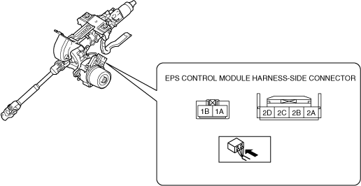
7. Attach the tester lead to the underside of the EPS CM connector and inspect the voltage according to the terminal voltage table (reference).
Terminal Voltage Table (Reference)
ac5uuw00003554
|
|
Terminal |
Signal name |
Connected to |
Measured item |
Measured terminal (measurement condition) |
Voltage (V) |
Inspection item(s) |
|---|---|---|---|---|---|---|
|
1A
|
Ground
|
Ground point
|
Voltage
|
Under any condition
|
1 or less
|
• Wiring harness (1A—ground point)
|
|
1B
|
Battery power supply
|
Battery
|
Voltage
|
Under any condition
|
B+
|
• Wiring harness (1B—battery)
• Fuse (EPAS 60A)
|
|
2A
|
Ignition power supply
|
IG1 relay
|
Voltage
|
Ignition ON (engine off or on)
|
B+
|
• Wiring harness (2A—IG1 relay—battery)
• Fuse (SRS1 7.5A)
|
|
Ignition OFF (LOCK)
|
1 or less
|
|||||
|
2B
|
CAN_H
|
—
|
Perform DTC inspection
|
—
|
||
|
2C
|
—
|
—
|
—
|
—
|
—
|
—
|
|
2D
|
CAN_L
|
—
|
Perform DTC inspection
|
—
|
||