49 N088 0A0
Fuel and thermometer checker
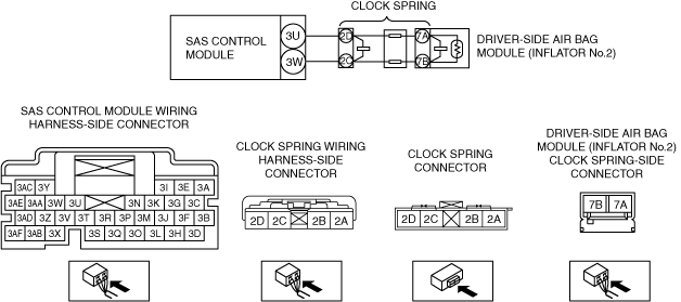
DTC B0002:11/B0002:12/B0002:13/B0002:19/B0002:1A [SAS CONTROL MODULE (TWO-STEP DEPLOYMENT CONTROL SYSTEM)]
id0802g8000200
Special Service Tool (SST)
|
49 N088 0A0
Fuel and thermometer checker
|
|
|
System malfunction location |
• B0002:11:Driver-side air bag module (inflator No.2) circuit short to body ground
• B0002:12:Driver-side air bag module (inflator No.2) circuit short to power supply
• B0002:13:Driver-side air bag module (inflator No.2) circuit open circuit or resistance high
• B0002:19:Short circuit to driver-side air bag module (inflator No.2) and other air bag module circuits
• B0002:1A:Driver-side air bag module (inflator No.2) circuit resistance low
|
|---|---|
|
Detection condition
|
• Resistance other than 1.37—6.33 ohms detected in the driver-side air bag module (inflator No.2) circuit
• Malfunction in the wiring harness between the driver-side air bag module (inflator No.2) and SAS control module
|
|
Fail-safe function
|
Not applicable
|
|
Possible cause
|
• Driver-side air bag module (inflator No.2) connector (clock spring-side) malfunction
• Clock spring malfunction
• Open circuit in the wiring harness between the following terminals:
• Short circuit to body ground in the wiring harness between the following terminals:
• Short circuit to power supply in the wiring harness between the following terminals:
• Short circuit to each other in the wiring harness between the clock spring and SAS control module
• Short circuit to other air bag module circuits in the wiring harness between the clock spring and SAS control module
• Driver-side air bag module malfunction
• SAS control module malfunction
|
 |
|
Diagnostic Procedure
|
Step |
Inspection |
Action |
|
|---|---|---|---|
|
1
|
INSPECT DRIVER-SIDE AIR BAG MODULE (INFLATOR NO.2) CONNECTOR
• Switch the ignition off.
• Disconnect the negative battery terminal and wait for 1 min or more.
• Remove the driver-side air bag module (inflator No.2) connector.
• Inspect the driver-side air bag module connector (clock spring-side). (Corrosion, damage, and disconnected pins)
• Is there any malfunction of the driver-side air bag module connector (clock spring-side)?
|
Yes
|
Replace clock spring.
Then go to Step 10.
|
|
No
|
Go to the next step.
|
||
|
2
|
INSPECT CLOCK SPRING
• Remove the steering wheel.
• Remove the column cover.
• Remove the clock spring.
• Inspect for continuity between the following terminals (clock spring-side):
• Is there continuity?
|
Yes
|
Go to the next step.
|
|
No
|
Replace clock spring.
Then go to Step 10.
|
||
|
3
|
INSPECT DRIVER-SIDE AIR BAG MODULE (INFLATOR NO.2) CIRCUIT FOR SHORT TO GROUND
• Remove the glove compartment.
• Disconnect the passenger-side air bag module connectors.
• Disconnect the driver and passenger-side front seat connectors.
• Remove the B-pillar lower trim.
• Disconnect the driver and passenger-side front pre-tensioner seat belt connectors.
• Remove the trunk side trim.
• Disconnect the driver and passenger-side rear pre-tensioner seat belt connectors.
• Remove the headliner.
• Disconnect the driver and passenger-side curtain air bag module connectors.
• Disconnect the all SAS control module connectors.
• Inspect for continuity between the following terminals (wiring harness-side) and body ground:
• Is there continuity?
|
Yes
|
Refer to the wiring diagram and verify whether or not there is a common connector between SAS control module terminal and clock spring terminal.
If there is a common connector:
• Determine the malfunctioning part by inspecting the common connector and the terminal for corrosion, damage, or pin disconnection, and the common wiring harness for a short to ground.
• Replace the malfunctioning part.
If there is no common connector:
• Replace the wiring harness which has a short to ground.
Go to Step 10.
|
|
No
|
Go to the next step.
|
||
|
4
|
INSPECT DRIVER-SIDE AIR BAG MODULE (INFLATOR NO.2) CIRCUIT FOR OPEN CIRCUIT
• SAS control module and clock spring connectors are disconnected.
• Inspect for continuity between the following terminals (wiring harness-side):
• Is there continuity?
|
Yes
|
Go to the next step.
|
|
No
|
Refer to the wiring diagram and verify whether or not there is a common connector between SAS control module terminal and clock spring terminal.
If there is a common connector:
• Determine the malfunctioning part by inspecting the common connector and the terminal for corrosion, damage, or pin disconnection, and the common wiring harness for an open circuit.
• Replace the malfunctioning part.
If there is no common connector:
• Replace the wiring harness which has an open circuit.
Go to Step 10.
|
||
|
5
|
INSPECT DRIVER-SIDE AIR BAG MODULE (INFLATOR NO.2) CIRCUIT FOR SHORT TO EACH OTHER
• SAS control module and clock spring connectors are disconnected.
• Inspect for continuity between the following terminals (wiring harness-side):
• Is there continuity?
|
Yes
|
Refer to the wiring diagram and verify whether or not there is a common connector between SAS control module terminal and clock spring terminal.
If there is a common connector:
• Determine the malfunctioning part by inspecting the common connector and the terminal for corrosion, damage, or pin disconnection, and the common wiring harness for a short to each other.
• Replace the malfunctioning part.
If there is no common connector:
• Replace the wiring harness which has a short to each other.
Go to Step 10.
|
|
No
|
Go to the next step.
|
||
|
6
|
INSPECT DRIVER-SIDE AIR BAG MODULE (INFLATOR NO.2) CIRCUIT FOR SHORT TO EACH OTHER
• Install the clock spring.
• SAS control module and driver-side air bag module (inflator No.2) connectors are disconnected.
• Inspect for continuity between the following terminals (wiring harness-side):
• Is there continuity?
|
Yes
|
Replace clock spring.
Then go to Step 10.
|
|
No
|
Go to the next step.
|
||
|
7
|
INSPECT DRIVER-SIDE AIR BAG MODULE (INFLATOR NO.2) CIRCUIT FOR SHORT TO OTHER AIR BAG MODULE CIRCUITS
• Remove the clock spring.
• SAS control module and clock spring connectors are disconnected.
• Other air bag module and pre-tensioner seat belt connectors are disconnected.
• Refer to the wiring diagram and inspect for continuity between the driver-side air bag module (inflator No.2) terminals and other air bag module or pre-tensioner seat belt terminals (wiring harness-side).
• Is there continuity?
|
Yes
|
Refer to the wiring diagram and verify whether or not there is a common connector between SAS control module terminal and clock spring terminal.
If there is a common connector:
• Determine the malfunctioning part by inspecting the common connector and the terminal for corrosion, damage, or pin disconnection, and the common wiring harness for a short to other air bag module or pre-tensioner seat belt circuits.
• Replace the malfunctioning part.
If there is no common connector:
• Replace the wiring harness which has a short to other air bag module or pre-tensioner seat belt circuits.
Go to Step 10.
|
|
No
|
Go to the next step.
|
||
|
8
|
INSPECT DRIVER-SIDE AIR BAG MODULE (INFLATOR NO.2) CIRCUIT FOR SHORT TO POWER SUPPLY
• SAS control module and clock spring connectors are disconnected.
• Connect the negative battery terminal.
• Switch the ignition ON (engine off or on).
• Measure the voltage at the following terminals (wiring harness-side):
• Is the voltage 0 V?
|
Yes
|
Go to the next step.
|
|
No
|
Refer to the wiring diagram and verify whether or not there is a common connector between SAS control module terminal and clock spring terminal.
If there is a common connector:
• Determine the malfunctioning part by inspecting the common connector and the terminal for corrosion, damage, or pin disconnection, and the common wiring harness for a short to power supply.
• Replace the malfunctioning part.
If there is no common connector:
• Replace the wiring harness which has a short to power supply.
Go to Step 10.
|
||
|
9
|
INSPECT DRIVER-SIDE AIR BAG MODULE (INFLATOR NO.2)
• Switch the ignition off.
• Disconnect the negative battery terminal and wait for 1 min or more.
• Connect the SAS control module connectors.
• Except for the driver-side air bag module (inflator No.2) connector, reconnect all disconnected connectors.
• Connect the SST (49 N088 0A0) or apply 2 ohms resistance to driver-side air bag module (inflator No.2) connector terminals 7A and 7B (clock spring-side).
• Set the SST (49 N088 0A0) to 2 ohms.
• Connect the negative battery terminal.
• Switch the ignition ON (engine off or on).
• Clear the DTC for the SAS control module using the M-MDS.
• Perform the DTC inspection for the SAS control module using the M-MDS.
• Are the same DTCs present?
|
Yes
|
Go to the next step.
|
|
No
|
Replace the driver-side air bag module.
Then go to the next step.
|
||
|
10
|
PERFORM SAS CONTROL MODULE DTC INSPECTION
• Switch the ignition off.
• Disconnect the negative battery terminal and wait for 1 min or more.
• Disconnect the SST (49 N088 0A0) or the 2 ohms resistance.
• Connect the driver-side air bag module (inflator No.2) connector.
• Connect the negative battery terminal.
• Switch the ignition ON (engine off or on).
• Clear the DTC for the SAS control module using the M-MDS.
• Perform the DTC inspection for the SAS control module using the M-MDS.
• Are the same DTCs present?
|
Yes
|
Repeat the inspection from Step 1.
• If the malfunction recurs, replace the SAS control module.
|
|
No
|
DTC troubleshooting completed.
|
||