 |
acxaaw00001617
ENGINE REMOVAL/INSTALLATION [L3 Turbo]
id0110b3800400
1. Remove the battery and battery tray. (See BATTERY REMOVAL/INSTALLATION [L3 Turbo].)
2. Remove the charge air cooler duct. (See INTAKE-AIR SYSTEM REMOVAL/INSTALLATION [L3 Turbo].)
3. Remove the air cleaner and fresh air duct component. (See INTAKE-AIR SYSTEM REMOVAL/INSTALLATION [L3 Turbo].)
4. Remove the front wheel and tire.
5. Remove the under cover, splash shield and mudguard.
6. Drain the engine coolant (SeeENGINE COOLANT REPLACEMENT [L3 Turbo].)
7. Drain the automatic transaxle fluid (ATF) (ATX). (See AUTOMATIC TRANSAXLE FLUID (ATF) REPLACEMENT [AW6A-EL, AW6AX-EL].)
8. Remove the drive belt. (See DRIVE BELT REMOVAL/INSTALLATION [L3 Turbo].)
9. Disconnect the heater hose. (See A/C UNIT REMOVAL/INSTALLATION [FULL-AUTO AIR CONDITIONER].)
10. Disconnect the radiator hose. (See RADIATOR REMOVAL/INSTALLATION [L3 Turbo].)
11. Disconnect the brake vacuum hose. (SeeVACUUM HOSE REMOVAL/INSTALLATION.)
12. Disconnect the fuel hose and vacuum hose. (See QUICK RELEASE CONNECTOR REMOVAL/INSTALLATION [L3 Turbo].)
13. Disconnect the selector cable from the transaxle side (ATX). (See SELECTOR LEVER COMPONENT REMOVAL/INSTALLATION.)
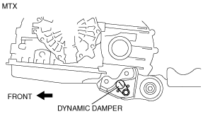
14. Disconnect the shift cable from the transaxle side (MTX). (See SHIFT MECHANISM REMOVAL/INSTALLATION [A26MX-R].)
15. Set the clutch release cylinder out of the way (MTX). (See CLUTCH RELEASE CYLINDER REMOVAL/INSTALLATION.)
16. Disconnect the wiring harnesses. (See PCM REMOVAL/INSTALLATION [L3 Turbo].)
17. Remove the propeller shaft (4WD). (See PROPELLER SHAFT REMOVAL/INSTALLATION.)
18. Remove the front pipe and HO2S. (See EXHAUST SYSTEM REMOVAL/INSTALLATION [L3 Turbo].)
19. Disconnect the front drive shaft (RH) from the joint shaft side. (See FRONT DRIVE SHAFT REMOVAL/INSTALLATION.)
20. Disconnect the front drive shaft (LH) from the transaxle side. (See FRONT DRIVE SHAFT REMOVAL/INSTALLATION.)
21. Remove the A/C compressor with the pipes still connected. (See A/C COMPRESSOR REMOVAL/INSTALLATION [FULL-AUTO AIR CONDITIONER].) (See A/C COMPRESSOR REMOVAL/INSTALLATION [MANUAL AIR CONDITIONER].)
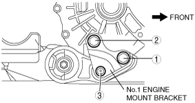
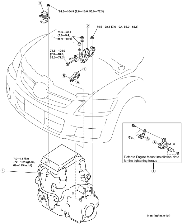
22. Remove in the order indicated in the figure.
23. Install in the reverse order of removal.
24. Start the engine, and inspect and adjust the following:
25. Perform a road test and verify that there is no abnormal vibration or noise.
acxaaw00001617
|
|
1
|
No.1 engine mount
|
|
2
|
No.4 engine mount bracket
|
|
3
|
No.3 engine mount rubber
|
|
4
|
Engine and transaxle
|
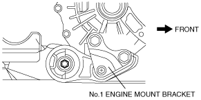
No.1 Engine Mount Removal Note
1. Remove the No.1 engine mount bracket from the underside of the vehicle.
acxaaw00001532
|
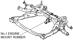
2. Remove the No.1 engine mount rubber and the front crossmember as a single unit. (See FRONT CROSSMEMBER REMOVAL/INSTALLATION [L.H.D.].) (See FRONT CROSSMEMBER REMOVAL/INSTALLATION [R.H.D.].)
acxuuw00000187
|
No.3 Engine Mount Rubber, No.4 Engine Mount Bracket Removal Note
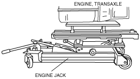
1. Secure the engine and transaxle using an engine jack.
acxaaw00001523
|
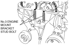
Engine Mount Installation Note
1. Tighten the No. 3 engine mount bracket stud bolt.
acxuuw00000189
|
2. Secure the engine and transaxle using an engine jack.
acxaaw00001523
|
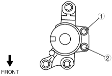
3. Temporarily tighten the No.1 engine mount bracket in the order shown in the figure.
acxaaw00001584
|
4. Temporarily tighten the No.3 engine mount nuts.
5. Tighten the No.3 engine mount nuts in the order shown in the figure.
acxuuw00000191
|
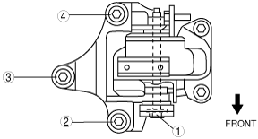
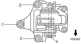
6. Temporarily tighten the No.4 engine mount bracket in the order shown in the figure.
ATX
acxuuw00000192
|
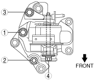
MTX
acxaaw00000928
|
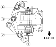
7. Tighten the No.4 engine mount bracket in the order shown in the figure.
ATX
acxuuw00000193
|
MTX
acxaaw00000929
|
Tightening torque
|
Installation position |
Tightening torque |
|---|---|
|
1―3
|
74.5—93.1 N·m {7.6—9.4 kgf·m, 55.0—68.6 ft·lbf}
|
|
4
|
74.5—104.9 N·m {7.6—10.6 kgf·m, 55.0—77.3 ft·lbf}
|
acxaaw00001232
|
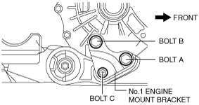
8. Tighten the No.1 engine mount bracket bolt A and B in order of A→B.
acxaaw00001591
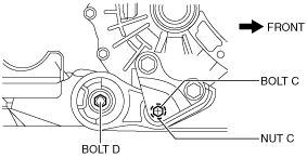
|
9. Tighten bolt C.
acxaaw00001620
|