1. : Mazda SST number
2. : Global SST number
1: 49 UN30 3050
2: 303–050
Engine lifting bracket
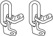
1: 49 C017 5A0
2: –
Engine support set
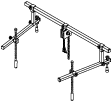
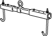
1: 49 L017 5A0
2: –
Support hanger
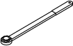
1: 49 JP01 001
2: –
Holder
—
—
TIMING CHAIN REMOVAL/INSTALLATION [SKYACTIV-D 2.2]
id0110s5801000
Special Service Tool (SST)
|
1. : Mazda SST number
2. : Global SST number
|
|||||
|
1: 49 UN30 3050
2: 303–050
Engine lifting bracket
|
|
1: 49 C017 5A0
2: –
Engine support set
|
|
1: 49 L017 5A0
2: –
Support hanger
|
|
|
1: 49 JP01 001
2: –
Holder
|
|
—
|
—
|
||
Replacement Part
|
Cylinder head cover gasket
Quantity: 1
Location of use: Cylinder head cover
|
Front oil seal
Quantity: 1
Location of use: Engine front cover
|
Gasket
Quantity: 1
Location of use: Water pipe
|
|
Washer
Quantity: 2
Location of use: Engine front cover
|
—
|
—
|
Oil and Chemical Type
|
Silicone sealant
Type: TB1217D or equivalent
|
Operation After Replacing Timing Chain
1. After replacing the timing chain, perform the following procedure.
|
STEP |
ACTION |
PAGE/CONDITION |
|---|---|---|
|
1
|
Perform KOEO self-test procedure.
|
|
|
2
|
Start the engine.
|
—
|
|
3
|
Verify that the check engine light does not illuminate.
|
—
|
|
4
|
Perform KOER self-test procedure.
|
|
|
5
|
Perform timing chain learning procedure.
|
|
|
6
|
Clear the DTCs.
|
|
|
7
|
Switch the ignition off.
|
—
|
|
8
|
Wait for 30 s or more.
|
—
|
Timing Chain Removal/Installation
ac5wzw00006607
|
ac5uuw00008427
|
1. Disconnect the negative battery terminal. (See NEGATIVE BATTERY TERMINAL DISCONNECTION/CONNECTION.)
2. Remove the engine cover. (See ENGINE COVER REMOVAL/INSTALLATION [SKYACTIV-D 2.2].)
3. Remove the front under cover No.2. (See FRONT UNDER COVER No.2 REMOVAL/INSTALLATION.)
4. Remove the front splash shield (RH). (See SPLASH SHIELD REMOVAL/INSTALLATION.)
5. Remove the drive belt. (See DRIVE BELT REMOVAL/INSTALLATION [SKYACTIV-D 2.2].)
6. Remove the drive belt auto tensioner. (See DRIVE BELT AUTO TENSIONER REMOVAL/INSTALLATION [SKYACTIV-D 2.2].)
7. Drain the engine oil. (See ENGINE OIL REPLACEMENT [SKYACTIV-D 2.2].)
8. Remove the oil pan. (See OIL PAN REMOVAL/INSTALLATION [SKYACTIV-D 2.2].)
9. Remove the fuel injectors. (See FUEL INJECTOR REMOVAL/INSTALLATION [SKYACTIV-D 2.2].)
10. Drain the engine coolant. (See ENGINE COOLANT REPLACEMENT [SKYACTIV-D 2.2].)
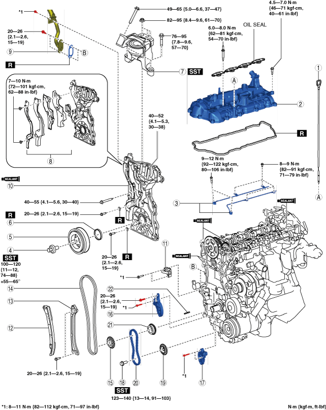
11. Remove in the order indicated in the table.
12. Install in the reverse order of removal.
13. Refill with the specified type and amount of the engine oil. (See ENGINE OIL REPLACEMENT [SKYACTIV-D 2.2].)
14. Refill the engine coolant. (See ENGINE COOLANT REPLACEMENT [SKYACTIV-D 2.2].)
15. Inspect for engine coolant leakage. (See ENGINE COOLANT LEAKAGE INSPECTION [SKYACTIV-D 2.2].)
16. If the timing chain is replaced, perform “Operation After Replacing Timing Chain”. (See Operation After Replacing Timing Chain.)
17. Start the engine and inspect the following:
ac8wzw00002497
|
|
1
|
Dipstick
|
|
2
|
Cylinder head cover
|
|
3
|
Oil shower pipe
|
|
4
|
Crankshaft pulley lock bolt
|
|
5
|
Crankshaft pulley
|
|
6
|
Front oil seal
|
|
7
|
No.3 engine mount
|
|
8
|
Noise suppression cover (No.1), noise suppression cover (No.2), seal rubber
|
|
9
|
Water pipe
|
|
10
|
Engine front cover
|
|
11
|
Timing chain tensioner
(See Timing chain removal note.)
|
|
12
|
Timing chain tensioner arm
(See Timing chain removal note.)
|
|
13
|
Timing chain guide
(See Timing chain removal note.)
|
|
14
|
Timing chain
(See Timing chain removal note.)
|
|
15
|
Crankshaft sprocket
(See Timing chain removal note.)
|
|
16
|
Oil pump chain tensioner No.2
(See Oil pump chain removal note.)
|
|
17
|
Oil pump chain tensioner No.1
(See Oil pump chain removal note.)
|
|
18
|
Oil pump driven sprocket installation bolt
(See Oil pump chain removal note.)
|
|
19
|
Oil pump driven sprocket
(See Oil pump chain removal note.)
|
|
20
|
Oil pump chain
(See Oil pump chain removal note.)
|
|
21
|
Oil pump drive sprocket
|
|
22
|
Key
|
Cylinder head cover removal note
1. Remove the fuel feed pipe. (See SUPPLY PUMP REMOVAL/INSTALLATION [SKYACTIV-D 2.2].)
2. Remove the injection pipe (supply pump side). (See INJECTION PIPE REMOVAL/INSTALLATION [SKYACTIV-D 2.2].)
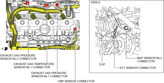
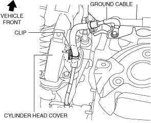
3. Set the wiring harness and ground cable aside using the following procedure:
ac5uuw00008429
|
ac5uuw00008430
|
ac8wzw00002498
|
ac8wzw00002499
|
ac5wzw00009353
|
4. Set the exhaust gas temperature sensor No.1 bracket aside.
ac8wzw00002500
|
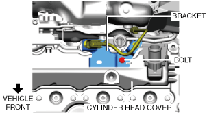
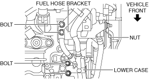
5. Set the lower case and fuel hose bracket aside using the following procedure:
ac8wzw00002501
|
ac5wzw00009355
|
6. Remove the cylinder head cover.
No.3 engine mount removal note
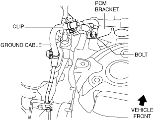
1. Remove the clip and bolt shown in the figure and set the ground cable aside.
ac8wzw00002502
|
2. Disconnect the active bonnet actuator connector (RH). (See ACTIVE BONNET ACTUATOR REMOVAL/INSTALLATION.)
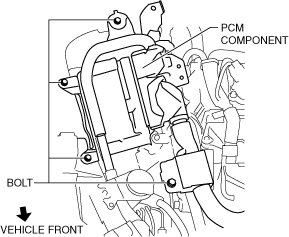
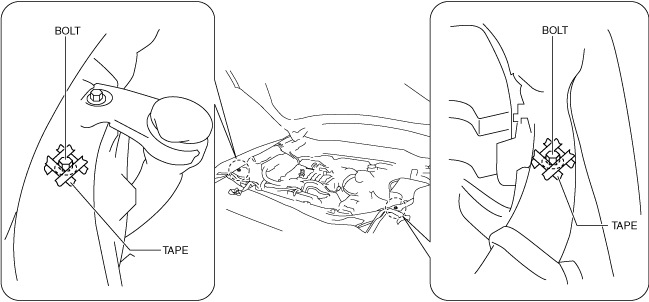
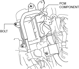
3. Remove the bolts shown in the figure and set the PCM component aside with the PCM connector connected.
ac8wzw00002503
|
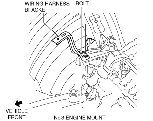
4. Remove the wiring harness bracket.
ac8wzw00002504
|
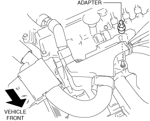
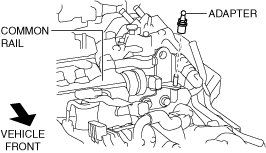
5. Remove the adapter shown in the figure.
ac5wzw00009361
|
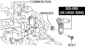
6. Install the SST to the position shown in the figure using the following bolt and washer.
ac5wzw00006590
|
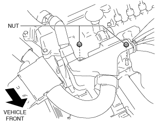
7. Remove the following parts.
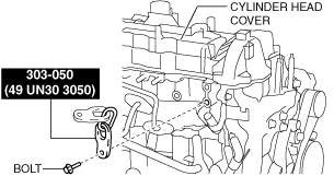
8. Install the SST to the position shown in the figure using the following bolt.
ac5wzw00006591
|
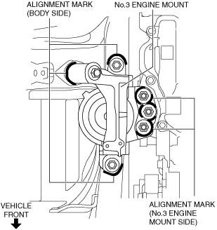
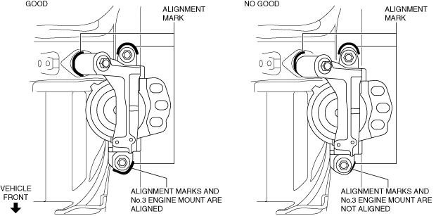
9. Place alignment marks on the locations shown in the figure so that they can be assembled to the same positions as before removal.
ac5wzw00009362
|
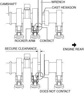
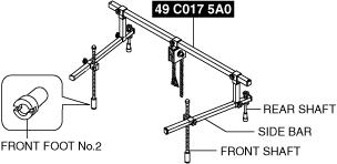
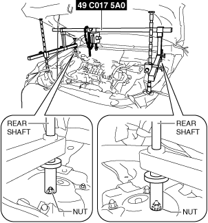
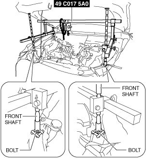
10. Install the SST using the following procedures.
ac5wzw00009363
|
ac5wzw00009364
|
ac5wzw00009365
|
ac5wzw00009366
|
ac5jjw00009739
|
ac5jjw00009740
|
11. Remove the No.3 engine mount.
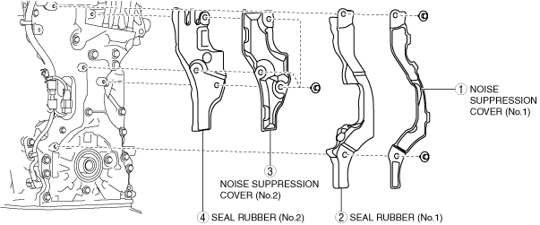
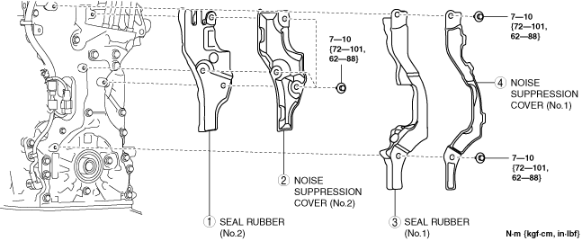
Noise suppression cover (No.1), noise suppression cover (No.2), seal rubber removal note
1. Remove the noise suppression covers and seal rubbers in the order shown in the figure.
ac5uuw00008436
|
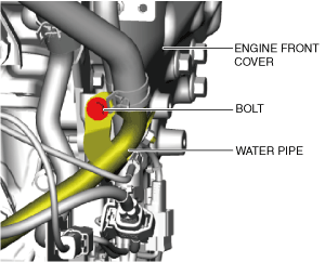
2. Remove the water pipe installation bolt shown in the figure.
ac8wzw00002505
|
3. Disconnect the connectors shown in the figure.
ac8wzw00002506
|
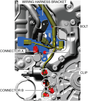
4. Remove the connectors, clips, and bolts shown in the figure and set the wiring harness and wiring harness bracket aside.
ac8wzw00002507
|
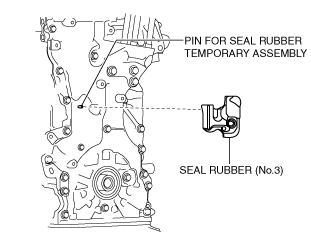
5. Remove the seal rubber (No.3) shown in the figure.
ac8wzw00002508
|
Engine front cover removal note
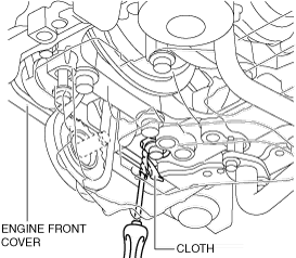
1. Remove the engine front cover installation bolts.
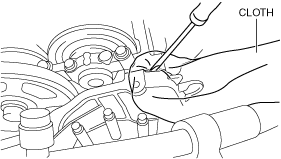
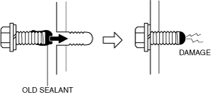
2. Using a screwdriver wrapped in a rag, peel the silicone sealant away a little at a time, and remove the engine front cover.
ac5wzw00005988
|
ac5wzw00005989
|
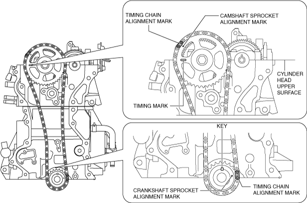
Timing chain removal note
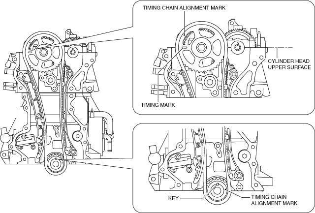
1. Rotate the crankshaft clockwise to adjust the timing marks and the key position as shown in the figure, and set cylinder No.1 at top dead center (TDC).
ac5wzw00005990
|
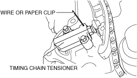
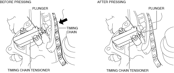
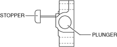
2. Release the tension on the timing chain using the following procedure:
ac5wzw00005991
|
ac5wzw00005566
|
ac5wzw00005992
|
3. Remove the timing chain tensioner and timing chain tensioner arm.
4. Remove the timing chain guide.
5. Remove the timing chain and crankshaft sprocket as a single unit.
Oil pump chain removal note
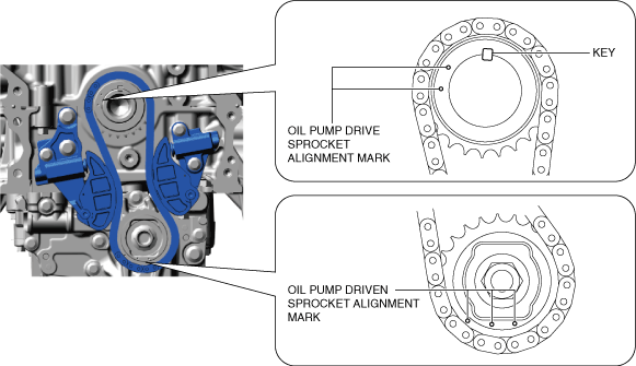
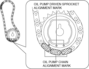
1. Verify that the oil pump driven sprocket alignment marks and key are aligned to the positions shown in the figure.
ac5uuw00009337
|
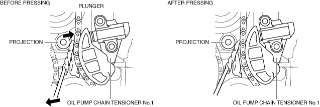
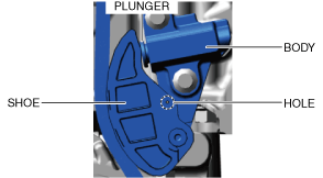
2. Release the tension on oil pump chain using the following procedure.
ac5uuw00009338
|
ac5uuw00009339
|
ac5uuw00009340
|
ac5uuw00009341
|
3. Remove the oil pump chain tensioner No.1 and No.2.
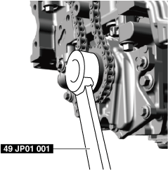
4. Remove the oil pump driven sprocket installation bolt using the following procedure.
ac8jjw00000508
|
5. Remove the oil pump chain and oil pump driven sprocket as a single unit.
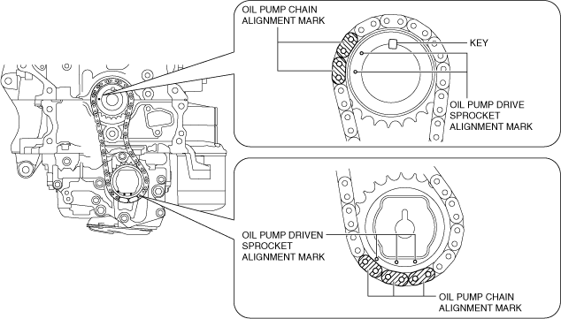
Oil pump chain installation note
1. Verify that the key and knock pin are aligned to the positions shown in the figure.
ac5uuw00009342
|
2. Align the oil pump chain alignment marks with the oil pump driven sprocket alignment marks.
ac5wzw00008954
|
3. Install the oil pump chain and oil pump driven sprocket as a single unit while aligning the alignment marks on each sprocket and oil pump chain as shown in the figure.
ac8wzw00003212
|
4. Temporarily tighten the oil pump driven sprocket installation bolt.
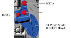
5. Install the oil pump chain tensioner No.1.
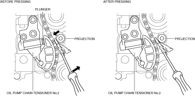
6. Install the oil pump chain tensioner No.2.
ac5uuw00009344
|
7. Tighten the oil pump driven sprocket installation bolt using the following procedure:
ac8jjw00000508
|
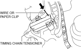
8. Remove the wire or paper clip installed to the oil pump chain tensioner and apply tension to the oil pump chain.
Timing chain installation note
1. Verify that the timing marks and the key are aligned to the position shown in the figure.
ac5wzw00005568
|
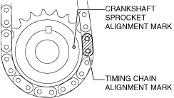
2. Align the timing chain alignment mark with the crankshaft sprocket alignment mark.
ac5wzw00008957
|
ac5wzw00008958
|
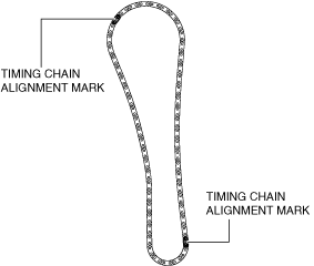
3. Install the timing chain and crankshaft sprocket as a single unit while aligning the marks on each sprocket and the timing chain as shown in the figure.
ac5wzw00008959
|
4. Install the timing chain guide.
5. Install the timing chain tensioner arm.
6. Install the timing chain tensioner.
7. After installing the timing chain tensioner, remove the installed wire or paper clip, and then apply tension to the timing chain.
ac5wzw00005996
|
8. Verify that there is no looseness in the timing chain, and re-verify that each sprocket is in the specified location.
9. Rotate the crankshaft clockwise two turns and inspect the valve timing.
ac5wzw00005990
|
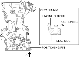
Engine front cover installation note
ac5wzw00005997
|
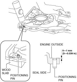
1. If the engine front cover is newly replaced, tap the positioning pins in the two locations to the seal surface side.
ac5wzw00005998
|
ac5wzw00005999
|
2. When reusing an engine front cover installation bolts, remove silicone sealant adhering to the bolts.
3. Completely clean and remove any oil, dirt, silicone sealant or other foreign matter that may be adhering to the engine front cover, cylinder head, and cylinder block.
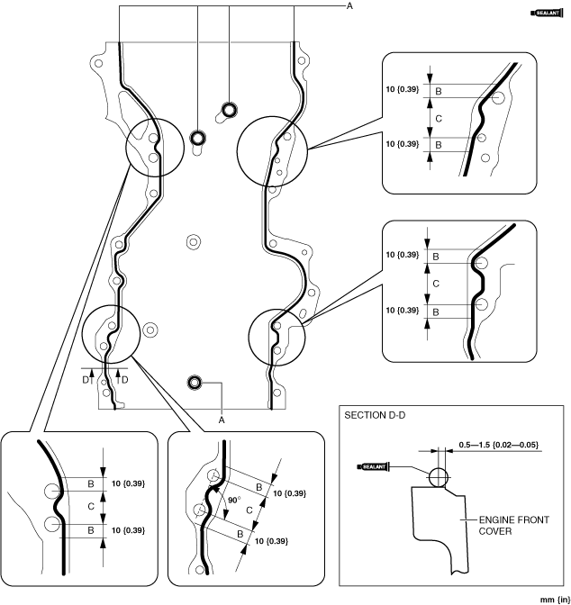
4. Apply silicone sealant (TB1217D or equivalent) to the engine front cover as shown in the figure.
ac8wzw00003213
|
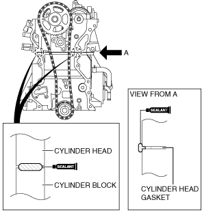
5. Apply silicone sealant (TB1217D or equivalent) to the areas shown in the figure.
ac5wzw00006001
|
6. Install the engine front cover to the engine.
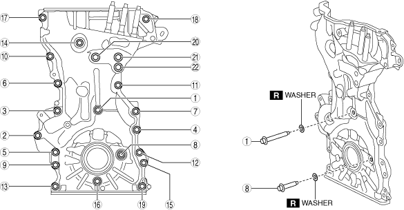
7. Tighten the engine front cover installation bolts in the order shown in the figure.
ac5wzw00006609
|
Tightening torque
|
Installation position |
Tightening torque |
|---|---|
|
1—19
|
20—26 N·m {2.1—2.6 kgf·m, 15—19 ft·lbf}
|
|
20—22
|
40—55 N·m {4.1—5.6 kgf·m, 30—40 ft·lbf}
|
8. Tighten the engine front cover stud bolts.
ac5wzw00006004
|
Noise suppression cover (No.1), noise suppression cover (No.2), seal rubber installation note
1. Temporarily put the seal rubber (No.3) on the engine front cover.
ac8wzw00002508
|
2. Connect the connectors and clips shown in the figure and install the wiring harness and wiring harness bracket.
ac8wzw00002507
|
3. Connect the connectors shown in the figure.
ac8wzw00002506
|
4. Tighten the water pipe installation bolt.
ac8wzw00002505
|
5. Install the noise suppression covers and seal rubbers in the order shown in the figure.
ac5uuw00008440
|
No.3 engine mount installation note
1. Temporarily tighten the No.3 engine mount installation bolts and nuts using the following procedure:
ac5wzw00009373
|
ac5wzw00009374
|
2. Tighten the No.3 engine mount installation bolts and nuts in the order shown in the figure.
ac5wzw00009375
|
Tightening torque
|
Installation position |
Tightening torque |
|---|---|
|
1
|
76—95 N·m {7.8—9.6 kgf·m, 57—70 ft·lbf}
|
|
2
|
82—95 N·m {8.4—9.6 kgf·m, 61—70 ft·lbf}
|
|
3
|
49—65 N·m {5.0—6.6 kgf·m, 37—47 ft·lbf}
|
3. Remove the SST.
4. Install the following parts.
5. Install the wiring harness bracket.
ac8wzw00002504
|
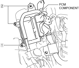
6. Install the PCM component using the following procedure:
ac8wzw00002509
|
ac8wzw00002510
|
ac8wzw00002511
|
7. Connect the active bonnet actuator connector (RH). (See ACTIVE BONNET ACTUATOR REMOVAL/INSTALLATION.)
8. Install the ground cable to the PCM bracket.
ac8wzw00002502
|
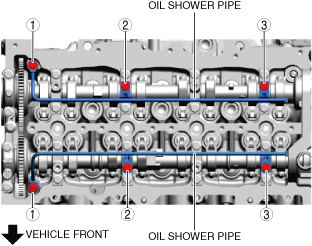
Oil shower pipe installation note
1. Install the oil shower pipe in the order shown in the figure.
ac5uuw00008441
|
Tightening torque
|
Installation position |
Tightening torque |
|---|---|
|
1
|
9—12 N·m {92—122 kgf·cm, 80—106 in·lbf}
|
|
2, 3
|
8.0—9.0 N·m {82—91 kgf·cm, 71—79 in·lbf}
|
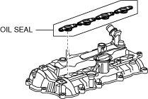
Cylinder head cover installation note
1. Install the oil seal on the cylinder head cover.
ac8wzw00002512
|
2. Insert a new cylinder head cover gasket into the cylinder head cover groove.
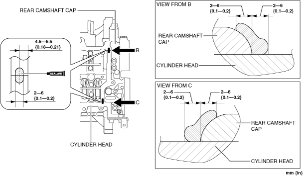
3. Apply silicone sealant (TB1217D or equivalent) to the areas shown in the figure.
Engine front side
ac5wzw00006610
|
Engine rear side
ac8wzw00002513
|
4. Install the cylinder head cover.
5. Tighten the cylinder head cover installation bolts using the following procedure:
ac8wzw00002514
|
aaxjjw00017854
|
aaxjjw00017855
|
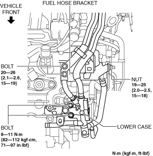
6. Install the lower case and fuel hose bracket using the following procedure:
ac5uuw00008446
|
ac8wzw00002501
|
7. Install the exhaust gas temperature sensor No.1 bracket.
ac8wzw00002500
|
8. Connect the wiring harness and ground cable using the following procedure:
ac8wzw00002499
|
ac5wzw00009353
|
ac8wzw00002498
|
ac5uuw00008430
|
ac5uuw00008429
|
9. Install the injection pipe (supply pump side). (See INJECTION PIPE REMOVAL/INSTALLATION [SKYACTIV-D 2.2].)
10. Install the fuel feed pipe. (See SUPPLY PUMP REMOVAL/INSTALLATION [SKYACTIV-D 2.2].)