Note
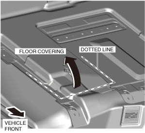
• Cut the floor covering to use the service hole.
ac8wzw00003783
|
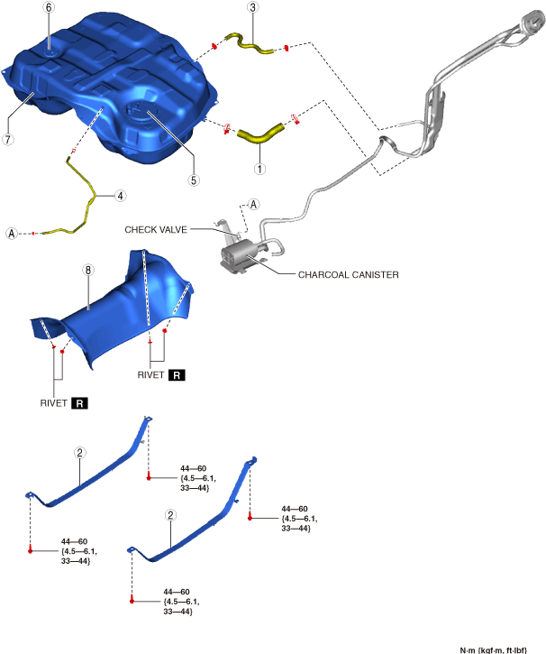
FUEL TANK REMOVAL/INSTALLATION [SKYACTIV-G 2.5]
id0114za801600
Replacement Part
|
Rivet
Quantity: 4
Location of use: Fuel tank insulator
|
2WD
1. Level the vehicle.
2. Complete the “BEFORE SERVICE PRECAUTION”. (See BEFORE SERVICE PRECAUTION [SKYACTIV-G 2.5].)
3. Drain the fuel. (See FUEL DRAINING PROCEDURE [SKYACTIV-G 2.5].)
4. Remove the second-row seat. (See SECOND-ROW SEAT REMOVAL/INSTALLATION.)
5. Cut the floor covering along the dotted lines shown in the figure and partially peel it back.
ac8wzw00003783
|
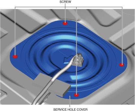
6. Remove the service hole cover.
ac8wzw00003784
|
7. Disconnect the following parts:
8. Remove the floor under cover. (See FLOOR UNDER COVER REMOVAL/INSTALLATION.)
9. Disconnect the HO2S connector.
10. Remove the TWC and HO2S as a single unit. (See EXHAUST SYSTEM REMOVAL/INSTALLATION [SKYACTIV-G 2.5].)
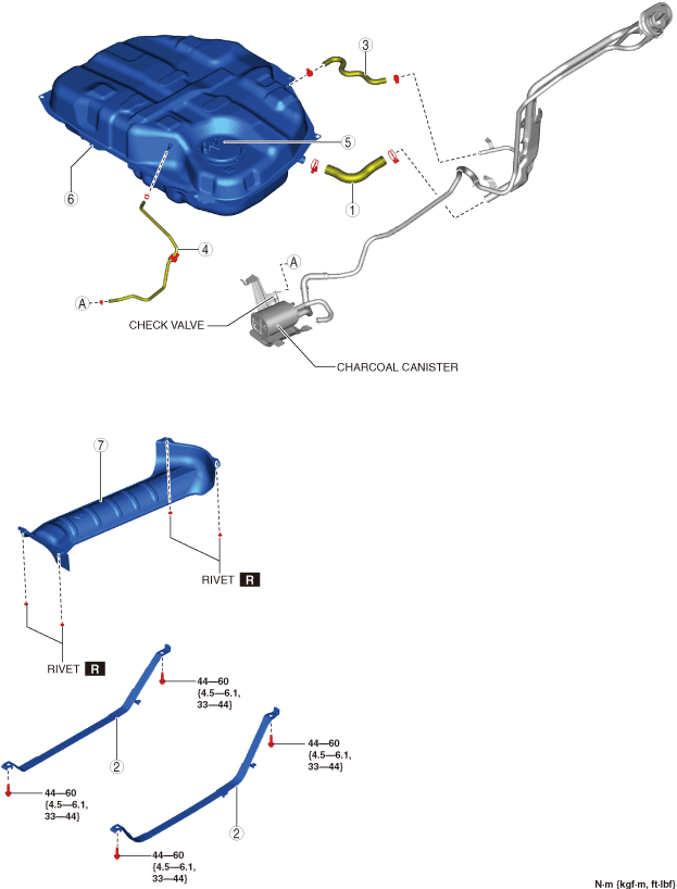
11. Remove in the order indicated in the table.
12. Install in the reverse order of removal.
13. Complete the “AFTER SERVICE PRECAUTION”. (See AFTER SERVICE PRECAUTION [SKYACTIV-G 2.5].)
ac8wzw00003785
|
|
1
|
Joint hose
(See Joint hose installation note.)
|
|
2
|
Fuel tank strap
|
|
3
|
Breather hose
|
|
4
|
Evaporative hose
|
|
5
|
Fuel pump unit
|
|
6
|
Fuel tank
(See Fuel tank removal note.)
|
|
7
|
Fuel tank insulator
|
4WD
1. Level the vehicle.
2. Complete the “BEFORE SERVICE PRECAUTION”. (See BEFORE SERVICE PRECAUTION [SKYACTIV-G 2.5].)
3. Drain the fuel. (See FUEL DRAINING PROCEDURE [SKYACTIV-G 2.5].)
4. Remove the second-row seat. (See SECOND-ROW SEAT REMOVAL/INSTALLATION.)
5. Cut the floor covering along the dotted lines shown in the figure and partially peel it back.
main side
ac8wzw00003783
|
sub side
ac8wzw00003786
|
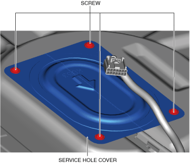
6. Remove the service hole cover.
Main side
ac8wzw00003784
|
Sub side
ac8wzw00003787
|
7. Disconnect the following parts:
8. Remove the floor under cover. (See FLOOR UNDER COVER REMOVAL/INSTALLATION.)
9. Disconnect the HO2S connector.
10. Remove the TWC and HO2S as a single unit. (See EXHAUST SYSTEM REMOVAL/INSTALLATION [SKYACTIV-G 2.5].)
11. Remove the propeller shaft. (See PROPELLER SHAFT REMOVAL/INSTALLATION.)
12. Remove in the order indicated in the table.
13. Install in the reverse order of removal.
14. Complete the “AFTER SERVICE PRECAUTION”. (See AFTER SERVICE PRECAUTION [SKYACTIV-G 2.5].)
ac8wzw00003788
|
|
1
|
Joint hose
(See Joint hose installation note.)
|
|
2
|
Fuel tank strap
|
|
3
|
Breather hose
|
|
4
|
Evaporative hose
|
|
5
|
Fuel pump unit
|
|
6
|
Fuel gauge sender unit (sub)
|
|
7
|
Fuel tank
(See Fuel tank removal note.)
|
|
8
|
Fuel tank insulator
|
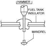
Fuel tank insulator removal note
1. Push out the mandrel using a hammer and punch (2—2.8 mm {0.08—0.11 in} diameter).
ac5wzw00002710
|
2. Remove the flange using a drill (5 mm {0.20 in} drill bit).
ar8uuw00001479
|
Fuel tank removal note
1. Disconnect the breather hose from the fuel-filler pipe.
2. Disconnect the evaporative hose from the check valve.
3. Remove the following parts as single unit.
4. Remove the fuel tank.
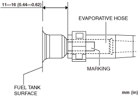
Evaporative Hose installation note
1. Install the evaporative hose as shown in the figure.
ac8wzw00003789
|
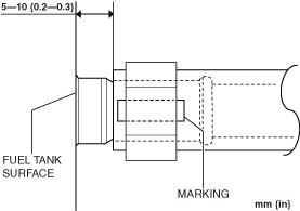
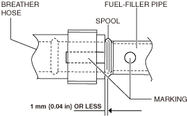
Breather hose installation note
1. Install the breather hose as shown in the figure.
Fuel tank side
ac8wzw00003790
|
Fuel-filler pipe side
ac8wzw00003791
|
Joint hose installation note
1. Install the joint hose as shown in the figure.
Fuel tank side
ac5uuw00000398
|
Fuel-filler pipe side
ac5wzw00013082
|