 |
ac8wzw00001506
STEERING GEAR AND LINKAGE REMOVAL/INSTALLATION
id061300801700
1. Remove the wheel and tire. (See WHEEL AND TIRE REMOVAL/INSTALLATION.)
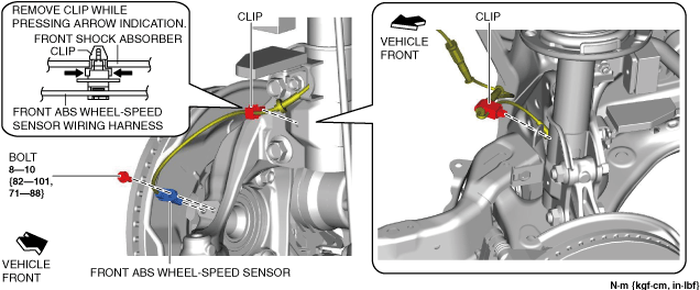
2. Disconnect the front ABS wheel-speed sensor wiring harness on the steering knuckle and set it aside so that it does not interfere with the servicing.
ac8wzw00001506
|
3. Remove the following parts.
4. Disconnect the tie-rod end from the steering knuckle. (See TIE-ROD END REPLACEMENT.)
5. Disconnect the front lower arm ball joint from the steering knuckle. (See FRONT LOWER ARM REMOVAL/INSTALLATION.)
6. Remove the joint cover. (See INTERMEDIATE SHAFT REMOVAL/INSTALLATION.)
7. Disconnect the intermediate shaft from the steering gear and linkage. (See INTERMEDIATE SHAFT REMOVAL/INSTALLATION.)
8. Remove the front crossmember component. (See FRONT CROSSMEMBER REMOVAL/INSTALLATION.)
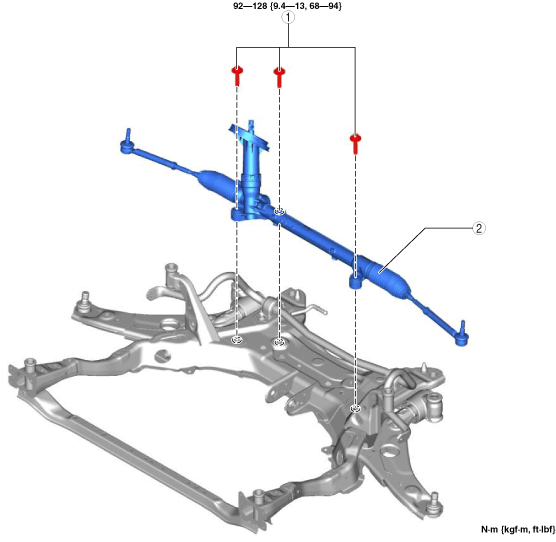
9. Remove in the order shown in the figure.
10. Install in the reverse order of removal.
11. After installation, inspect the front wheel alignment. (See FRONT WHEEL ALIGNMENT.)
ac8wzw00001507
|
|
1
|
Steering gear and linkage installation bolt
|
|
2
|
Steering gear and linkage
|
Steering Gear and Linkage Removal Note
1. Move the steering gear and linkage in the direction of the arrow in the order shown in the figure and remove it.
ac8jjw00001358
|
Steering Gear and Linkage Installation Bolt Installation Note
1. Temporarily tighten the steering gear and linkage installation bolts.
2. Tighten the steering gear and linkage installation bolts to the specified torque.