 |
ac8wzw00000871
FRONT FENDER STAY REMOVAL/INSTALLATION
id091000803900
Front Fender Stay (LH)
1. Disconnect the negative battery terminal. (See NEGATIVE BATTERY TERMINAL DISCONNECTION/CONNECTION.)
2. Remove the following parts:
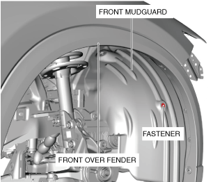
3. Remove the fastener.
ac8wzw00000871
|
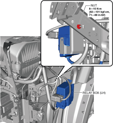
4. Remove the nut.
ac8wzw00000872
|
5. Remove the relay box (LH).
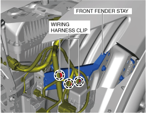
6. Remove the wiring harness clips.
ac8wzw00000873
|
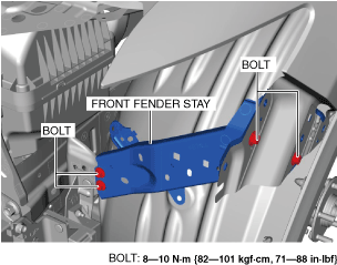
7. Remove the bolts.
ac8wzw00000874
|
8. Remove the front fender stay.
9. Install in the reverse order of removal. (See Front Fender Stay Replacement Note.)
10. Perform the headlight aiming adjustment. (See HEADLIGHT AIMING.)
Front Fender Stay (RH)
1. Disconnect the negative battery terminal. (See NEGATIVE BATTERY TERMINAL DISCONNECTION/CONNECTION.)
2. Remove the following parts:
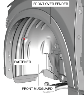
3. Remove the fastener.
ac8wzw00000875
|
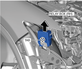
4. Detach the tab and remove the relay box (RH) in the direction of the arrow shown in the figure.
ac8wzw00000876
|
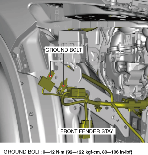
5. Remove the ground bolts.
ac8wzw00000877
|
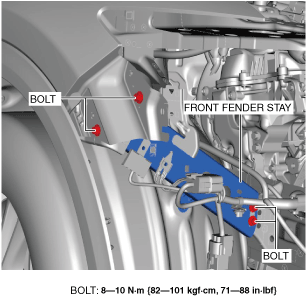
6. Remove the bolts.
ac8wzw00000878
|
7. Remove the front fender stay.
8. Install in the reverse order of removal. (See Front Fender Stay Replacement Note.)
9. Perform the headlight aiming adjustment. (See HEADLIGHT AIMING.)
Front Fender Stay Replacement Note