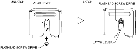
LIFTGATE LOCK ACTUATOR INSPECTION


id091400512100

1.  Disconnect the negative battery terminal. (See NEGATIVE BATTERY TERMINAL DISCONNECTION/CONNECTION.)

2.  Remove the following parts:

(1)  Liftgate upper trim (See LIFTGATE UPPER TRIM REMOVAL/INSTALLATION.)
(2)  Liftgate side trim (See LIFTGATE SIDE TRIM REMOVAL/INSTALLATION.)
(3)  Liftgate recess (See LIFTGATE RECESS REMOVAL/INSTALLATION.)
(4)  Power liftgate (PLG) rear switch (with power liftgate (PLG) system) (See POWER LIFTGATE (PLG) REAR SWITCH REMOVAL/INSTALLATION.)
(5)  Liftgate lower trim (See LIFTGATE LOWER TRIM REMOVAL/INSTALLATION.)
(6)  Liftgate latch and lock actuator (See LIFTGATE LATCH AND LOCK ACTUATOR REMOVAL/INSTALLATION.)

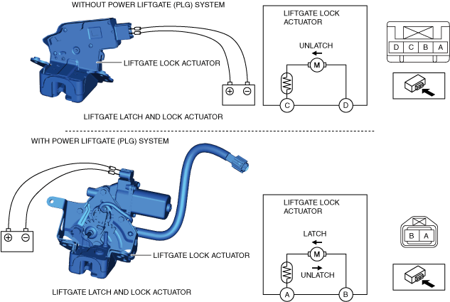
3.  Apply battery positive voltage and connect the ground to the liftgate latch and lock actuator terminals as indicated in the table below and verify the operation condition.

ac8wzw00001211

Without power liftgate (PLG) system

Liftgate lock actuator operation

Connection

C

D

UNLATCH
Ground
B+

With power liftgate (PLG) system

Liftgate lock actuator operation

Connection

A

B

UNLATCH
B+
Ground
LATCH
Ground
B+

•  If the operation cannot be verified, replace the liftgate latch and lock actuator. (See LIFTGATE LATCH AND LOCK ACTUATOR REMOVAL/INSTALLATION.)

Note
•  Press in the latch lever of the liftgate latch and lock actuator (Without power liftgate (PLG) system) using a flathead screwdriver, and set it to the latched condition.
ac8wzw00001212