 |
ac8wzw00003910
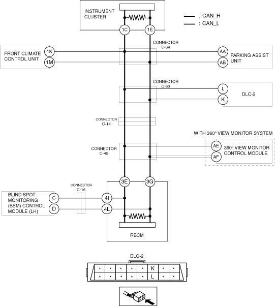
DETERMINING SHORT TO POWER SUPPLY LOCATION (MS-CAN) [L.H.D.]
id100225001000
System Wiring Diagram
ac8wzw00003910
|
Determination Procedure
|
Step |
Inspection |
Action |
|
|---|---|---|---|
|
1
|
INSPECT FOR SHORT TO POWER SUPPLY BETWEEN CONNECTOR INSTRUMENT CLUSTER AND REAR BODY CONTROL MODULE (RBCM)
• Disconnect the negative battery terminal.
• Disconnect the rear body control module (RBCM).
• Connect the negative battery terminal.
• Switch the ignition ON (engine off).
• Measure the voltage at DLC-2 terminals L and K.
• Is the voltage between 1.5 — 3.5 V?
|
Yes
|
Go to the next step.
|
|
No
|
Go to Step 4.
|
||
|
2
|
INSPECT FOR SHORT TO POWER SUPPLY BETWEEN BLIND SPOT MONITORING (BSM) CONTROL MODULE (LH) AND REAR BODY CONTROL MODULE (RBCM)
• Measure the voltage at blind spot monitoring (BSM) control module (LH) terminals C and D.
• Is the voltage between 1.5 — 3.5 V?
|
Yes
|
Replace the rear body control module (RBCM) because there is a short to the power supply in the rear body control module (RBCM).
|
|
No
|
Go to Step 4.
|
||
|
3
|
INSPECT FOR SHORT TO POWER SUPPLY BETWEEN BLIND SPOT MONITORING (BSM) CONTROL MODULE (LH) AND CONNECTOR C-16
• Switch the ignition off (LOCK).
• Disconnect the negative battery terminal.
• Disconnect the instrument cluster connector.
• Connect connector C-16.
• Connect the negative battery terminal.
• Switch the ignition ON (engine off).
• Measure the voltage at blind spot monitoring (BSM) control module (LH) terminals C and D.
• Is the voltage between 1.5 — 3.5 V?
|
Yes
|
Repair or replace the wiring harness between the rear body control module (RBCM) and connector C-16 because the wiring harness is shorted to the power supply.
|
|
No
|
Go to the next step.
|
||
|
4
|
INSPECT BLIND SPOT MONITORING (BSM) CONTROL MODULE (LH) FOR SHORT TO POWER SUPPLY
• Measure the voltage at blind spot monitoring (BSM) control module (LH) terminals C and D.
• Is the voltage between 1.5 — 3.5 V?
|
Yes
|
Replace the blind spot monitoring (BSM) control module (LH) because there is a short to power supply in the blind spot monitoring (BSM) control module (LH).
|
|
No
|
Repair or replace the wiring harness between the blind spot monitoring (BSM) control module (LH) and connector C-16 because the wiring harness is shorted to power supply.
|
||
|
5
|
INSPECT FOR SHORT TO POWER SUPPLY BETWEEN CONNECTOR C-45 AND INSTRUMENT CLUSTER
• Disconnect the negative battery terminal.
• Disconnect connector C-45
• Connect the negative battery terminal.
• Switch the ignition ON (engine off).
• Measure the voltage at DLC-2 terminals L and K.
• Is the voltage between 1.5 — 3.5 V?
|
Yes
|
With 360° view monitor control module
• Go to Step 15.
Without 360° view monitor control module
• Repair or replace the wiring harness between the rear body control module (RBCM) and connector C-45 because the wiring harness is shorted to power supply.
|
|
No
|
Go to the next step.
|
||
|
6
|
INSPECT FOR SHORT TO POWER SUPPLY BETWEEN CONNECTOR C-14 AND INSTRUMENT CLUSTER
• Disconnect the negative battery terminal.
• Disconnect connector C-14
• Connect the negative battery terminal.
• Switch the ignition ON (engine off).
• Measure the voltage at DLC-2 terminals L and K.
• Is the voltage between 1.5 — 3.5 V?
|
Yes
|
Repair or replace the wiring harness between connector C-14 and connector C-45 because the wiring harness is shorted to power supply.
|
|
No
|
Go to the next step.
|
||
|
7
|
INSPECT FOR SHORT TO POWER SUPPLY BETWEEN CONNECTOR C-63 AND INSTRUMENT CLUSTER
• Disconnect the negative battery terminal.
• Disconnect connector C-63
• Connect the negative battery terminal.
• Switch the ignition ON (engine off).
• Measure the voltage at DLC-2 terminals L and K.
• Is the voltage between 1.5 — 3.5 V?
|
Yes
|
Go to the next step.
|
|
No
|
Repair or replace the wiring harness between connector C-63 and DLC-2 because the wiring harness is shorted to power supply.
|
||
|
8
|
INSPECT FOR SHORT TO POWER SUPPLY BETWEEN CONNECTOR C-14 AND CONNECTOR C-63
• Switch the ignition off (LOCK).
• Disconnect the negative battery terminal.
• Disconnect the connector C-14.
• Connect connector C-63.
• Connect the negative battery terminal.
• Switch the ignition ON (engine off).
• Measure the voltage at rear body control module (RBCM) terminals 3E and 3G.
• Is the voltage between 1.5 — 3.5 V?
|
Yes
|
Go to the next step.
|
|
No
|
Repair or replace the wiring harness between connector C-14 and connector C-63 because the wiring harness is shorted to power supply.
|
||
|
9
|
INSPECT FOR SHORT TO POWER SUPPLY BETWEEN CONNECTOR C-63 AND CONNECTOR C-64
• Switch the ignition off (LOCK).
• Disconnect the negative battery terminal.
• Disconnect the connector C-63.
• Connect connector C-64.
• Connect the negative battery terminal.
• Switch the ignition ON (engine off).
• Measure the voltage at DLC-2 terminals L and K.
• Is the voltage between 1.5 — 3.5 V?
|
Yes
|
Go to the next step.
|
|
No
|
Repair or replace the wiring harness between connector C-63 and connector C-64 because the wiring harness is shorted to power supply.
|
||
|
10
|
INSPECT FOR SHORT TO POWER SUPPLY BETWEEN CONNECTOR C-63 AND FRONT CLIMATE CONTROL UNIT
• Measure the voltage at front climate control unit terminals 1K and 1M.
• Is the voltage between 1.5 — 3.5 V?
|
Yes
|
Go to Step 12.
|
|
No
|
Go to the next step.
|
||
|
11
|
INSPECT FRONT CLIMATE CONTROL UNIT FOR SHORT TO POWER SUPPLY
• Switch the ignition off (LOCK).
• Disconnect the negative battery terminal.
• Disconnect the front climate control unit connector.
• Connect connector C-64.
• Connect the negative battery terminal.
• Switch the ignition ON (engine off).
• Measure the voltage at DLC-2 terminals L and K.
• Is the voltage between 1.5 — 3.5 V?
|
Yes
|
Replace the front climate control unit because there is a short to power supply in the front climate control unit.
|
|
No
|
Repair or replace the wiring harness between the front climate control unit and connector C-64 because the wiring harness is shorted to power supply.
|
||
|
12
|
INSPECT FOR SHORT TO POWER SUPPLY BETWEEN CONNECTOR C-64 AND PARKING ASSIST UNIT
• Measure the voltage at parking assist unit terminals AA and AB.
• Is the voltage between 1.5 — 3.5 V?
|
Yes
|
Go to Step 14.
|
|
No
|
Go to the next step.
|
||
|
13
|
INSPECT PARKING ASSIST UNIT FOR SHORT TO POWER SUPPLY
• Switch the ignition off (LOCK).
• Disconnect the negative battery terminal.
• Connect connector C-64.
• Disconnect the rear body control module (RBCM) connector.
• Connect the negative battery terminal.
• Switch the ignition ON (engine off).
• Measure the voltage at parking assist unit terminals AA and AB.
• Is the voltage between 1.5 — 3.5 V?
|
Yes
|
Replace the parking assist unit because there is a short to power supply in the parking assist unit.
|
|
No
|
Repair or replace the wiring harness between the parking assist unit and connector C-64 because the wiring harness is shorted to power supply.
|
||
|
14
|
INSPECT INSTRUMENT CLUSTER FOR SHORT TO POWER SUPPLY
• Switch the ignition off (LOCK).
• Disconnect the negative battery terminal.
• Disconnect the instrument cluster connector.
• Connect connector C-64.
• Connect the negative battery terminal.
• Switch the ignition ON (engine off).
• Measure the voltage at DLC-2 terminals L and K.
• Is the voltage between 1.5 — 3.5 V?
|
Yes
|
Replace the instrument cluster because there is a short to power supply in the instrument cluster.
|
|
No
|
Repair or replace the wiring harness between the instrument cluster and connector C-64 because the wiring harness is shorted to power supply.
|
||
|
15
|
INSPECT FOR SHORT TO POWER SUPPLY BETWEEN CONNECTOR C-45 AND 360° VIEW MONITOR CONTROL MODULE
• Measure the voltage at 360° view monitor control module terminals AE and AF.
• Is the voltage between 1.5 — 3.5 V?
|
Yes
|
Repair or replace the wiring harness between the rear body control module (RBCM) and connector C-45 because the wiring harness is shorted to power supply.
|
|
No
|
Go to the next step.
|
||
|
16
|
INSPECT 360° VIEW MONITOR CONTROL MODULE FOR SHORT TO POWER SUPPLY
• Switch the ignition off (LOCK).
• Disconnect the negative battery terminal.
• Disconnect the 360° view monitor control module connector.
• Connect connector C-45.
• Connect the negative battery terminal.
• Switch the ignition ON (engine off).
• Measure the voltage at DLC-2 terminals L and K.
• Is the voltage between 1.5 — 3.5 V?
|
Yes
|
Replace the 360° view monitor control module because there is a short to power supply in the 360° view monitor control module.
|
|
No
|
Repair or replace the wiring harness between the 360° view monitor control module and connector C-45 because the wiring harness is shorted to power supply.
|
||