|
1
|
VERIFY RELATED SERVICE INFORMATION AVAILABILITY
• Verify related Service Information availability.
• Is any related Service Information available?
|
Yes
|
Perform repair or diagnosis according to the available Service Information.
• If the vehicle is not repaired, go to the next step.
|
|
No
|
Go to the next step.
|
|
2
|
VERIFY RELATED PENDING CODE AND/OR DTC
• Turn the ignition switch off, then to the ON position (engine off).
• Perform the Pending Trouble Code Access Procedure and DTC Reading Procedure.
• Is the PENDING CODE/DTC P0572:00, P0573:00 or P1703:00 also present?
|
Yes
|
Go to the applicable PENDING CODE or DTC inspection.
|
|
No
|
Go to the next step.
|
|
3
|
CHECK OPERATION OF STOP LIGHT
• Turn the ignition switch to the ON position (engine off).
• Apply and release the brake pedal and check the stop light operation.
• Do the stop light operate correctly?
|
Yes
|
Go to the next step.
|
|
No
|
Inspect the stop light.
• If the stop light is normal, go to the next step.
• If the stop light is not normal, repair or replace malfunctioning part, then go to Step 11.
|
|
4
|
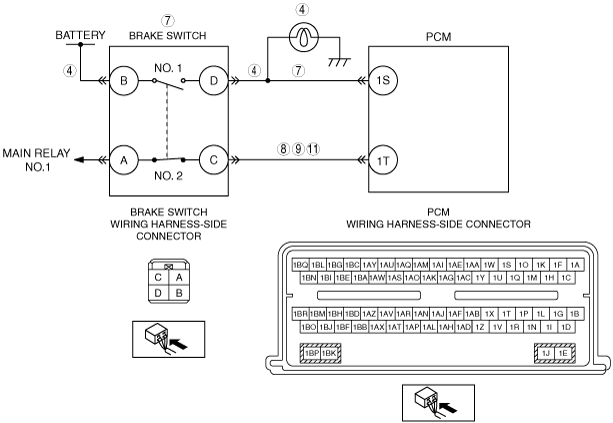
CHECK BRAKE SWITCH NO.1 OPERATION
• Access the PCM and monitor the BOO PID.
• Apply and release the brake pedal while monitoring the BOO PID.
• Does the PID cycle ON and OFF?
|
Yes
|
Go to Step 7.
|
|
No
|
Go to the next step.
|
|
5
|
CHECK FOR BRAKE SWITCH NO.1 CIRCUIT CYCLING
• Turn the ignition switch off.
• Disconnect the PCM connector.
• Turn the ignition switch to the ON position (engine off).
• Apply and release the brake pedal while monitoring the voltage.
• Measure the voltage between PCM terminal 1S (wiring harness-side) and body ground.
• Is voltage less than 1 V with the brake pedal released and greater than 10 V with the brake pedal fully applied?
|
Yes
|
Unable to duplicate or identify the cause of concern at this time.
Perform the “INTERMITTENT CONCERN TROUBLESHOOTING” procedure.
|
|
No
|
Go to the next step.
|
|
6
|
CHECK BRAKE SWITCH NO.1 CIRCUIT FOR OPEN
-
Caution
-
• Inspect the brake switch with it installed to the brake pedal, otherwise the brake switch may not operate normally. If the brake switch is removed from the brake pedal, replace the brake switch with a new one.
• PCM connector is disconnected.
• Turn the ignition switch off.
• Disconnect the brake switch connector.
• Measure the resistance between brake switch terminal D (wiring harness-side) and PCM terminal 1S (wiring harness-side).
• Is the resistance less than 5 ohm?
|
Yes
|
Replace the brake switch, then go to Step 11.
|
|
No
|
Repair for open circuit, then go to Step 11.
|
|
7
|
CHECK FOR BRAKE SWITCH NO.2 CIRCUIT CYCLING
• Turn the ignition switch off.
• Disconnect the PCM connector.
• Turn the ignition switch to the ON position (engine off).
• Apply and release the brake pedal while monitoring the voltage.
• Measure the voltage between PCM terminal 1T and body ground.
• Is voltage greater than 10 V with the brake pedal released and less than 1 volt with the brake pedal fully applied?
|
Yes
|
Unable to duplicate or identify the cause of concern at this time.
Perform the “INTERMITTENT CONCERN TROUBLESHOOTING” procedure.
|
|
No
|
Go to the next step.
|
|
8
|
CHECK BRAKE SWITCH NO.2 CIRCUIT FOR SHORT TO POWER
-
Caution
-
• Inspect the brake switch with it installed to the brake pedal, otherwise the brake switch may not operate normally. If the brake switch is removed from the brake pedal, replace the brake switch with a new one.
• PCM connector is disconnected.
• Turn the ignition switch off.
• Disconnect the brake switch connector.
• Measure the voltage between PCM terminal 1T (wiring harness-side) and body ground.
• Is there any voltage?
|
Yes
|
Repair for short circuit, then go to Step 11.
|
|
No
|
Go to the next step.
|
|
9
|
CHECK BRAKE SWITCH NO.2 CIRCUIT FOR SHORT TO GROUND
• Brake switch and PCM connectors are disconnected.
• Measure the resistance between PCM terminal 1T (wiring harness-side) and body ground.
• Is the resistance less than 5 ohm?
|
Yes
|
Repair for short circuit, then go to Step 11.
|
|
No
|
Go to the next step.
|
|
10
|
CHECK BRAKE SWITCH NO.2 CIRCUIT FOR OPEN
• Brake switch and PCM connectors are disconnected.
• Measure the resistance between brake switch terminal C (wiring harness-side) and PCM terminal 1T (wiring harness-side).
• Is the resistance less than 5 ohm?
|
Yes
|
Replace the brake switch, then go to the next step.
|
|
No
|
Repair for open circuit, then go to the next step.
|
|
11
|
VERIFY TROUBLESHOOTING OF DTC P0504:00 HAS BEEN COMPLETED
• Verify that all disconnected connectors are reconnected.
• Clear the DTC from the PCM memory using the M-MDS.
• Depress and release the brake pedal more than 5 times.
• Retrieve the DTC using the M-MDS.
• Is the same DTC present?
|
Yes
|
Repeat the inspection from Step 1.
• If the malfunction recurs, replace the PCM.
Go to the next step.
|
|
No
|
Go to the next step.
|
|
12
|
VERIFY AFTER REPAIR PROCEDURE
• Perform the “AFTER REPAIR PROCEDURE”.
• Are any DTCs present?
|
Yes
|
Go to the applicable DTC inspection.
|
|
No
|
Troubleshooting completed.
|