CONTROL VALVE BODY REMOVAL/INSTALLATION [AY6A-EL, AY6AX-EL]
id0517k3331900
-
Warning
-
• A hot transaxle and ATF can cause severe burns. Turn off the engine and wait until they are cool.
• Using compressed air can cause dirt and other particles to fly out, causing injury to the eyes. Wear protective eyeglasses whenever using compressed air.
-
Caution
-
• Water or foreign objects entering the connector can cause a poor connection or corrosion. Be sure not to drop water or foreign objects on the connector when disconnecting it.
1. Disconnect the negative battery cable.
2. Remove the fresh-air duct and air cleaner component as a single unit. (See INTAKE-AIR SYSTEM REMOVAL/INSTALLATION [MZI-3.7].)
3. Remove the air cleaner bracket. (See INTAKE-AIR SYSTEM REMOVAL/INSTALLATION [MZI-3.7].)
4. Clean the transaxle exterior throughout with a steam cleaner or cleaning solvents.
5. Drain the ATF. (See AUTOMATIC TRANSAXLE FLUID (ATF) REPLACEMENT [AY6A-EL, AY6AX-EL].)
6. Disconnect the oil hose from the oil cooler. (See OIL COOLER REMOVAL/INSTALLATION [AY6A-EL, AY6AX-EL].)
7. Disconnect the oil cooler from the transaxle with the water hose connected, and set it out of the way. (See OIL COOLER REMOVAL/INSTALLATION [AY6A-EL, AY6AX-EL].)
8. Disconnect the oil hose from the oil pipe component (transaxle side). (See OIL COOLER REMOVAL/INSTALLATION [AY6A-EL, AY6AX-EL].)
9. Remove the oil pipe component (transaxle side). (See OIL COOLER REMOVAL/INSTALLATION [AY6A-EL, AY6AX-EL].)
10. Remove the control valve body cover. (See CONTROL VALVE BODY COVER REPLACEMENT [AY6A-EL, AY6AX-EL].)
-
Note
-
• Disconnect the solenoid connector according to the following procedure:
-
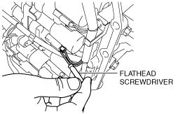
i. Insert a precision flathead screwdriver from the backside into the connector as shown in the figure.
-
Caution
-
• Do not damage the solenoid valves and connectors with the flathead screwdriver.
ii. Pry the flathead screwdriver in the direction of the arrow and disconnect the connector.
-
Caution
-
• When disconnecting connectors, grasp the connectors, not the wiring harnesses. Otherwise, the wiring harnesses may be pulled out of the connector causing poor contact.
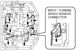
11. Disconnect the solenoid connectors, VSS connector and the input/turbine speed sensor connector.
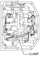
12. Disconnect the coupler component from the clamp.
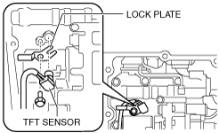
13. Remove the lock plate, and pull out the TFT sensor from the control valve body.
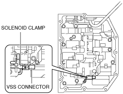
14. Remove the VSS connector from the solenoid clamp.
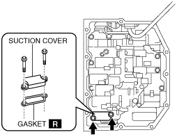
15. Remove the suction cover and the gasket.
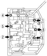
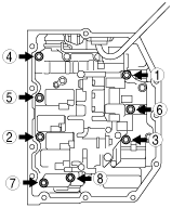
16. Remove the control valve body installation bolts in the order shown in the figure.
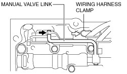
17. Disconnect the manual valve link and remove the control valve body component.
-
Caution
-
• Do not drop the control valve body component.
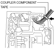
18. Fix the coupler component with tape to the transaxle case as shown in the figure.
-
Note
-
• Be sure to secure the coupler component with tape so that it will not interfere with the control valve body component.
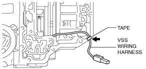
19. Fix the VSS wiring harness with tape to the transaxle case as shown in the figure.
-
Note
-
• Be sure to secure the VSS with tape so that they will not interfere with the control valve body component.
20. Connect the manual valve link and install the control valve body component.
-
Caution
-
• When installing the control valve body component, secure the coupler component to the wiring harness clamp.
• Do not pinch the coupler component between the transaxle case and the control valve body component.
21. Temporarily install the control valve body component with the bolts.
-
Note
-
• Aligning the bolt holes, temporarily tighten the bolt by hand.
-
Bolt length (measured from below the head)
-
A: 21 mm {0.83 in}
B: 31 mm {1.2 in}
22. Temporarily install the suction cover and a new gasket with the bolts.
-
Note
-
• Aligning the bolt holes, temporarily tighten the bolt by hand.
23. Tighten the bolts in the order shown in the figure.
-
Tightening torque
-
8—12 N·m {82—122 kgf·cm, 71—106 in·lbf}
24. Install the connector of the VSS to the solenoid clamp.
25. Install the TFT sensor with the lock plate and a bolt to the control valve body component as shown in the figure.
-
Tightening torque
-
6.0—8.0 N·m {62—81 kgf·cm, 54—70 in·lbf}
26. Connect the solenoid connectors, VSS connector and the input/turbine speed sensor connector.
27. Connect the coupler component to the clamps.
28. Install the new control valve body cover. (See CONTROL VALVE BODY COVER REPLACEMENT [AY6A-EL, AY6AX-EL].)
29. Install the oil pipe component (transaxle side). (See OIL COOLER REMOVAL/INSTALLATION [AY6A-EL, AY6AX-EL].)
30. Connect the oil hose to the oil pipe component (transaxle side). (See OIL COOLER REMOVAL/INSTALLATION [AY6A-EL, AY6AX-EL].)
31. Install the oil cooler to the transaxle. (See OIL COOLER REMOVAL/INSTALLATION [AY6A-EL, AY6AX-EL].)
32. Connect the oil hose to the oil cooler. (See OIL COOLER REMOVAL/INSTALLATION [AY6A-EL, AY6AX-EL].)
33. Install the air cleaner bracket. (See INTAKE-AIR SYSTEM REMOVAL/INSTALLATION [MZI-3.7].)
34. Add ATF. (See AUTOMATIC TRANSAXLE FLUID (ATF) LEVEL ADJUSTMENT [AY6A-EL, AY6AX-EL].)
35. Install the fresh-air duct and air cleaner component as a single unit. (See INTAKE-AIR SYSTEM REMOVAL/INSTALLATION [MZI-3.7].)
36. Connect the negative battery cable.
37. Adjust the ATF level. (See AUTOMATIC TRANSAXLE FLUID (ATF) LEVEL ADJUSTMENT [AY6A-EL, AY6AX-EL].)
38. Perform the “MECHANICAL SYSTEM TEST”. (See MECHANICAL SYSTEM TEST [AY6A-EL, AY6AX-EL].)
39. Perform the “ROAD TEST”. (See ROAD TEST [AY6A-EL, AY6AX-EL].)
 am6xuw00004105
 am6xuw00004106