|
ac9wzw00003231
CYLINDER HEAD GASKET REPLACEMENT [MZI-3.7]
id0110c5800700
1. Drain the engine oil. (See ENGINE OIL REPLACEMENT [MZI-3.7].)
2. Remove the engine and transaxle component. (See ENGINE REMOVAL/INSTALLATION [MZI-3.7].)
3. Secure the engine and transaxle component using a hoist and the SST.
ac9wzw00003231
|
4. Remove the dynamic chamber and throttle body as a single unit. (See INTAKE-AIR SYSTEM REMOVAL/INSTALLATION [MZI-3.7].)
5. Remove the fuel injector and fuel distributor together as a single unit. (See FUEL INJECTOR REMOVAL/INSTALLATION [MZI-3.7].)
6. Remove the thermostat and thermostat housing together as a single unit. (See THERMOSTAT REMOVAL/INSTALLATION [MZI-3.7].)
7. Remove the Intake manifold. (See INTAKE-AIR SYSTEM REMOVAL/INSTALLATION [MZI-3.7].)
8. Remove both WU-TWCs together with both exhaust manifolds as a single unit. (See EXHAUST SYSTEM REMOVAL/INSTALLATION [MZI-3.7].)
9. Remove the ignition coils. (See IGNITION COIL REMOVAL/INSTALLATION [MZI-3.7].)
10. Remove the dipstick.
11. Remove the power steering oil pump drive belt. (See DRIVE BELT REMOVAL/INSTALLATION [MZI-3.7].)
12. Remove the power steering oil pump. (See POWER STEERING OIL PUMP REMOVAL/INSTALLATION [L.H.D.].) (See POWER STEERING OIL PUMP REMOVAL/INSTALLATION [R.H.D.].)
13. Remove the generator. (See GENERATOR REMOVAL/INSTALLATION [MZI-3.7].)
14. Remove the OCV component (LH) (RH). (See TIMING CHAIN REMOVAL/INSTALLATION [MZI-3.7].)
15. Remove in the order indicated in the table.
16. Install in the reverse order of removal.
17. Start the engine and:
18. Perform a road test.
ac9wzw00003232
|
|
1
|
Timing chain component
|
|
2
|
Camshaft cap (LH)
|
|
3
|
Camshaft timing chain tensioner (LH)
|
|
4
|
Camshaft timing chain (LH)
|
|
5
|
Camshaft component (LH)
|
|
6
|
Camshaft cap (RH)
|
|
7
|
Camshaft timing chain tensioner (RH)
|
|
8
|
Camshaft timing chain (RH)
|
|
9
|
Camshaft component (RH)
|
|
10
|
Cylinder head (LH)
(See Cylinder Head Removal Note.)
|
|
11
|
Cylinder head gasket (LH)
|
|
12
|
Cylinder head (RH)
(See Cylinder Head Removal Note.)
|
|
13
|
Cylinder head gasket (RH)
|
Timing chain Component Removal Note
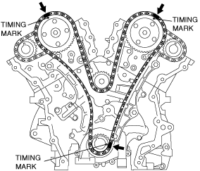
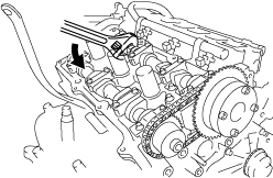
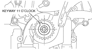
1. Turn the crankshaft clockwise so that the crankshaft keyway is in the 11 o’clock position. (This will position the No.1 cylinder at TDC.)
ac9wzw00003233
|
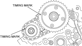
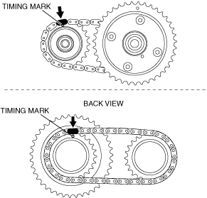
2. Mark the timing chain at the position of each timing sprocket timing mark.
ac9wzw00003234
|
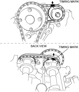
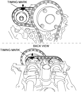
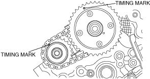
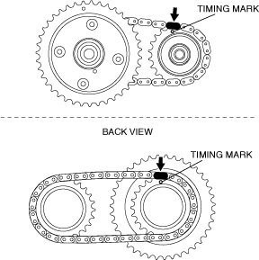
3. Mark the camshaft timing chain at the positions where it is aligned with each of the camshaft sprocket on both banks.
LH
ac9wzw00003235
|
RH
ac9wzw00003236
|
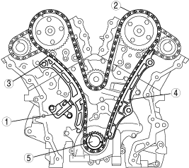
4. Remove the timing chain in the following order.
ac9wzw00003237
|
Camshaft Component Removal Note
1. Rotate the crankshaft counterclockwise until the keyway is in the 9 o'clock position.
ac9wzw00003238
|
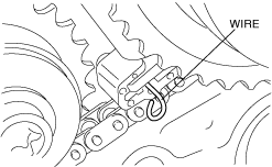
2. Slowly compress the camshaft timing chain tensioner (LH) piston by hand.
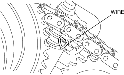
3. Insert an approx. 1.0 mm {0.039 in} thin wire or paper clip into the camshaft timing chain tensioner (LH) shown in the figure to hold the tensioner piston.
ac9wzw00003239
|
4. Verify that the camshafts (LH) are in the neutral position.
ac9wzw00003240
|
5. Loosen the LH bank camshaft cap bolts in several passes in the order shown in the figure and remove the camshaft cap.
ac9wzw00003241
|
6. Remove the camshaft, camshaft sprocket, camshaft timing chain, and camshaft timing chain tensioner of the LH bank as a single unit.
7. Slowly compress the camshaft timing chain tensioner (RH) piston by hand.
8. Insert an approx. 1.0 mm {0.039 in} thin wire or paper clip into the camshaft timing chain tensioner (RH) shown in the figure to hold the tensioner piston.
ac9wzw00003242
|
9. Put a wrench to the position shown in the figure on the RH bank camshaft, rotate the RH bank camshaft counterclockwise, and set the camshaft to the neutral position.
ac9wzw00003243
|
ac9wzw00003244
|
10. Loosen the RH bank camshaft cap bolts in several passes in the order shown in the figure and remove the camshaft cap.
ac9wzw00003245
|
11. Remove the camshaft, camshaft sprocket, camshaft timing chain, and camshaft timing chain tensioner of the RH bank as a single unit.
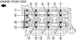
Cylinder Head Removal Note
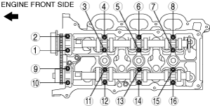
1. Loosen the cylinder head bolts in several passes in the order shown.
ac9wzw00003246
|
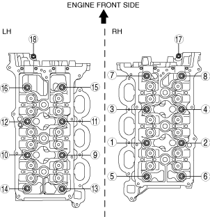
Cylinder Head Installation Note
1. Tighten the cylinder head bolts in the order in 6 steps in the order shown in the figure.
ac9wzw00003247
|
Tightening torque
|
Step |
Installation position |
Tightening torque |
|---|---|---|
|
1
|
1—16
|
20 N·m {2.0 kgf·m, 15 ft·lbf}
|
|
2
|
1—16
|
35 N·m {3.6 kgf·m, 26 ft·lbf}
|
|
3
|
1—16
|
90 °
|
|
4
|
1—16
|
90 °
|
|
5
|
1—16
|
90 °
|
|
6
|
17, 18
|
8.5—11.5 N·m {87—117 kgf·cm, 76—101 in·lbf}
|
Camshaft Component Installation Note
1. Assemble the camshaft timing chain tensioners on both sides.
2. Install the camshaft component (RH).
RH
ac9wzw00005865
|
ac9wzw00003244
|
ac9wzw00003249
|
ac9wzw00003250
|
ac9wzw00003251
|
ac9wzw00003252
|
ac9wzw00005866
|
3. Install the camshaft component (LH).
LH
ac9wzw00003254
|
ac9wzw00003240
|
ac9wzw00003255
|
ac9wzw00003256
|
4. Turn the crankshaft clockwise so that the crankshaft keyway is in the 11 o’clock position. (This will position the No.1 cylinder at TDC.)
ac9wzw00003257
|
Timing chain Component Installation Note
1. Follow the “TIMING CHAIN REMOVAL/INSTALLATION” procedure and install the timing chain. (See TIMING CHAIN REMOVAL/INSTALLATION [MZI-3.7].)