 |
ac9wzw00001545
ENGINE REMOVAL/INSTALLATION [MZI-3.7]
id0110c5800400
1. Perform “Fuel Line Safety Procedures”. Leave the fuel pump relay removed. (See BEFORE SERVICE PRECAUTION [MZI-3.7].)
2. Disconnect both battery cables.
3. Remove the battery and battery tray. (See BATTERY REMOVAL/INSTALLATION [MZI-3.7].)
4. Drain the power steering fluid. (See POWER STEERING FLUID INSPECTION.)
5. Drain the engine coolant. (See ENGINE COOLANT REPLACEMENT [MZI-3.7].)
6. Remove the engine cover. (See ENGINE COVER REMOVAL/INSTALLATION [MZI-3.7].)
7. Remove the ventilation hose. (See QUICK RELEASE CONNECTOR (EMISSION SYSTEM) REMOVAL/INSTALLATION [MZI-3.7].)
8. Disconnect the vacuum hose. (See INTAKE-AIR SYSTEM REMOVAL/INSTALLATION [MZI-3.7].)
9. Remove the air cleaner. (See INTAKE-AIR SYSTEM REMOVAL/INSTALLATION [MZI-3.7].)
10. Remove the resonance chamber. (See INTAKE-AIR SYSTEM REMOVAL/INSTALLATION [MZI-3.7].)
11. Remove the both front wheels and tires. (See GENERAL PROCEDURES (SUSPENSION).)
12. Remove the splash shield (RH).
13. Remove the generator and A/C drive belt. (See DRIVE BELT REMOVAL/INSTALLATION [MZI-3.7].)
14. Disconnect the front drive shaft (RH) from the joint shaft side. (See FRONT DRIVE SHAFT REMOVAL/INSTALLATION.)
15. Disconnect the front drive shaft (LH) from the transaxle side. (See FRONT DRIVE SHAFT REMOVAL/INSTALLATION.)
16. Remove the front pipe and middle pipe as a single unit. (See EXHAUST SYSTEM REMOVAL/INSTALLATION [MZI-3.7].)
17. Position the propeller shaft out of the way. (See PROPELLER SHAFT REMOVAL/INSTALLATION.)
18. Disconnect the selector cable from the transaxle side. (See AUTOMATIC TRANSAXLE REMOVAL/INSTALLATION [AW6AX-EL].)
19. Disconnect the heater hose. (See HEATER PIPE AND HOSE COMPONENT REMOVAL/INSTALLATION.)
20. Remove the engine hanger installation bolt, and power steering oil pump hose out of the way (R.H.D.). (See POWER STEERING OIL PUMP REMOVAL/INSTALLATION [R.H.D.].)
21. Disconnect the power steering return hose. (See POWER STEERING OIL PUMP REMOVAL/INSTALLATION [L.H.D.].) (See POWER STEERING OIL PUMP REMOVAL/INSTALLATION [R.H.D.].)
22. Disconnect the radiator hose. (See RADIATOR REMOVAL/INSTALLATION [MZI-3.7].)
23. Disconnect the water hose. (See OIL COOLER REMOVAL/INSTALLATION [MZI-3.7].)
24. Disconnect the ATF oil cooler hose.
25. Disconnect the plastic fuel hose. (See BEFORE SERVICE PRECAUTION [MZI-3.7].) (See QUICK RELEASE CONNECTOR (EMISSION SYSTEM) REMOVAL/INSTALLATION [MZI-3.7].)
26. Disconnect the wiring harness.
27. Remove the A/C compressor with the pipes connected and secure the A/C compressor using wire or rope so that it is out of the way. (See A/C COMPRESSOR REMOVAL/INSTALLATION.)
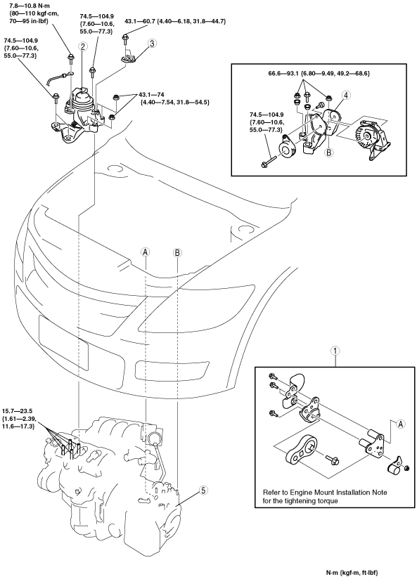
28. Remove the engine and transaxle component using an engine jack in the order indicated in the figure.
29. Install in the reverse order of removal.
30. Start the engine and:
31. Perform a road test.
ac9wzw00001545
|
|
1
|
No.1 engine mount
|
|
2
|
No.3 engine mount rubber
|
|
3
|
No.3 engine mount stay (No.3 engine mount side)
|
|
4
|
No.4 engine mount bracket
|
|
5
|
Engine and transaxle
|
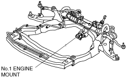
No.1 Engine Mount Removal Note
1. Remove the front under cover A and front under cover B. (See FRONT UNDER COVER REMOVAL/INSTALLATION.)
2. Remove the transverse member. (See TRANSVERSE MEMBER REMOVAL/INSTALLATION.)
3. Remove the intermediate shaft installation bolt, and disconnect the steering shaft. (See STEERING WHEEL AND COLUMN REMOVAL/INSTALLATION.)
4. Remove the No.1 engine mounting bracket bolts.
ac9wzw00000697
|
5. Remove the No.1 engine mount, No.1 engine mount bracket and the front crossmember as a single unit. (See FRONT CROSSMEMBER REMOVAL/INSTALLATION [L.H.D.].) (See FRONT CROSSMEMBER REMOVAL/INSTALLATION [R.H.D.].)
ac9wzw00000784
|
No.3 Engine Mount Rubber and No.4 Engine Mount Bracket Removal Note
1. Secure the engine and transaxle using an engine jack and attachment.
acxuuw00000188
|
2. Secure the engine, transaxle, and crossmember component using a hoist.
Engine and Transaxle Removal Note
ac9uuw00000223
|
Engine Mount Installation Note
1. Tighten the No.3 engine mount stud bolts.
ac9wzw00000785
|
2. Secure the engine and the transaxle using an engine jack and attachment as shown.
ac9uuw00000220
|
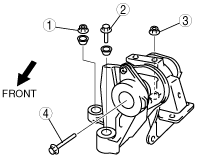
3. Temporarily tighten the No.3 engine mount bolt and nuts in the order shown in the figure.
ac9uuw00000222
|
4. Temporarily tighten the No. 4 engine mount bracket in two passes.
ac9uuw00000890
|
ac9uuw00000233
|
5. Install the No.1 engine mount, No.1 engine mount bracket and the front crossmember as a single unit. (See FRONT CROSSMEMBER REMOVAL/INSTALLATION [L.H.D.].) (See FRONT CROSSMEMBER REMOVAL/INSTALLATION [R.H.D.].)
ac9wzw00000784
|
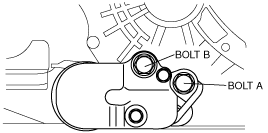
6. Tighten the No.1 engine mount bracket bolt A and B in order of A→B.
ac9wzw00000787
|
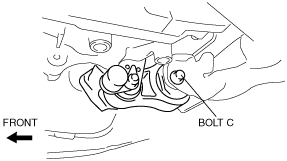
7. Tighten the No.1 engine mount bolt C at the specified torque.
ac9uuw00003036
|
8. Install the intermediate shaft installation bolt, and disconnect the steering shaft. (See STEERING WHEEL AND COLUMN REMOVAL/INSTALLATION.)
9. Install the transverse member. (See TRANSVERSE MEMBER REMOVAL/INSTALLATION.)
10. Install the front under cover A and front under cover B. (See FRONT UNDER COVER REMOVAL/INSTALLATION.)
11. Tighten the No.3 engine mount in the order shown in the figure.
ac9uuw00000222
|
Tightening Torque
|
Installation Position |
Tightening Torque |
|---|---|
|
1, 2, 7
|
74.5—104.9 N·m {7.60—10.6 kgf·m, 55.0—77.3 ft·lbf}
|
|
3, 4, 5, 6
|
43.1—74 N·m {4.40—7.54 kgf·m, 31.8—54.5 ft·lbf}
|
12. Tighten the No.3 engine mount stay (No.3 engine mount side).
13. Tighten the No.4 engine mount in the order shown in the figure.
ac9uuw00000231
|
Tightening Torque
|
Installation Position |
Tightening Torque |
|---|---|
|
1, 2, 3
|
66.6—93.1 N·m {6.80—9.49 kgf·m, 49.2—68.6 ft·lbf}
|
|
4
|
74.5—104.9 N·m {7.60—10.6 kgf·m, 55.0—77.3 ft·lbf}
|