 |
a30zzw00002141
FRONT DRIVE SHAFT REMOVAL/INSTALLATION
id031300700300
Replacement part
|
Locknut
Quantity: 1
Location of use: Front drive shaft
|
Snap pin
Quantity: 1
Location of use: Tie-rod end
|
Oil and chemical type
|
Grease
Type: D4Y0 33247 or equivalent
|
1. Remove the wheel and tire. (See WHEEL AND TIRE REMOVAL/INSTALLATION.)
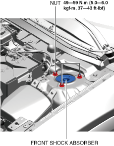
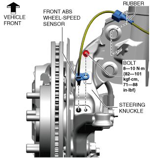
2. Disconnect the rubber from the front shock absorber.
a30zzw00002141
|
3. Disconnect the front ABS wheel-speed sensor wiring harness on the steering knuckle and set it aside so that it does not interfere with the servicing.
4. Remove the front under cover No.2. (See FRONT UNDER COVER No.2 REMOVAL/INSTALLATION.)
5. Remove the front deflector. (See DEFLECTOR REMOVAL/INSTALLATION.)
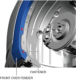
6. Remove the fasteners shown in the figure and slightly bend back the front over fender.
azzjjb00000611
|
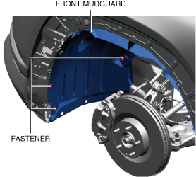
7. Remove the fasteners shown in the figure and slightly bend back the front mudguard.
a30zzw00002142
|
8. Remove the front splash shield. (See SPLASH SHIELD REMOVAL/INSTALLATION.)
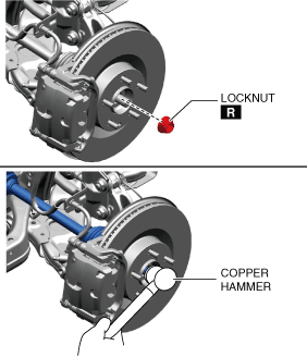
9. Remove the locknut with the brake pedal depressed. (See Locknut Installation Note)
a30zzw00002143
|
10. Temporarily install a spare nut to the front drive shaft.
11. Tap the nut with a copper hammer and separate the front drive shaft from the axle.
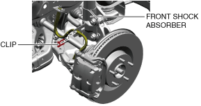
12. Remove the clip from the front shock absorber. (See FRONT BRAKE HOSE REMOVAL/INSTALLATION.)
a30zzw00002144
|
13. Loosen the Front shock absorber installation nut.
a30zzw00002145
|
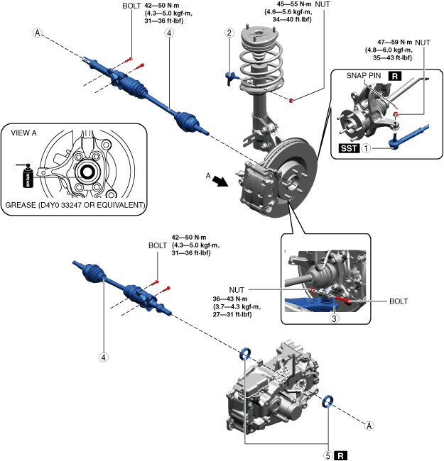
14. Remove in the order shown in the figure.
15. Install in the reverse order of removal.
16. After installing the front drive shaft, inspect the ATF level. (See AUTOMATIC TRANSAXLE FLUID (ATF) INSPECTION [A71M].)
a30zzw00004287
|
|
1
|
Tie-rod end
|
|
2
|
Front stabilizer control link (upper side)
|
|
3
|
Front lower arm ball joint
|
|
4
|
Front drive shaft
|
|
5
|
Oil seal (differential)
|
Bracket, Front Drive Shaft Installation Note
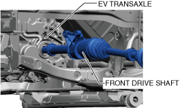
1. Install the front drive shaft to the EV transaxle.
a30zzw00002146
|
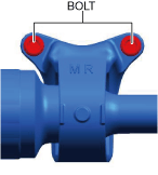
2. Temporarily tighten bolt shown in the figure.
a30zzw00002147
|
3. Completely tighten bolt shown in the figure.
4. Apply ATF to the oil seal lip.
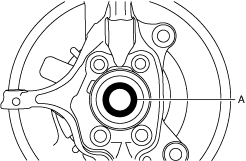
5. Apply grease (D4Y0 33247 or equivalent) to the wheel bearing inner race and front drive shaft contact surfaces (area A in the figure).
am3zzw00034658
|
6. Insert the front drive shaft to the wheel hub.
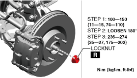
Locknut Installation Note
1. If dust or grease is on the drive shaft thread area, wipe it off with a cloth.
2. Working with two people, one should depress and hold the pedal down.
3. While the brake pedal is depressed, the other should tighten the locknut using the following procedure.
a30zzw00002148
|