BRAKE SYSTEM WARNING LIGHT TURNS ON [ELECTRONICALLY CONTROLLED BRAKE SYSTEM]
id040309070500
Outline
Description |
Brake system warning light turns on |
|
---|---|---|
Possible cause
|
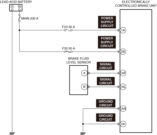
• Brake fluid level is low
• Brake fluid level sensor stuck on
• Short to ground in brake fluid level sensor signal circuit
• Electronically controlled brake unit connector is disconnected (circuit that turns on ABS warning light, TCS/DSC operation indicator light, brake system warning light, and TCS OFF indicator light if electronically controlled brake unit connector is disconnected)
• Electronically controlled brake unit detects malfunction (input/output device malfunction)
• Electronically controlled brake unit detects decrease in power supply voltage
• Poor ground in electronically controlled brake unit (If electronically controlled brake unit ground is not secured properly, ABS warning light, TCS/DSC operation indicator light, brake warning light, and TCS OFF indicator light turn on, but no DTC is output)
• Electronically controlled brake unit does not activate
• Electronically controlled brake unit internal malfunction
• Instrument cluster malfunction
|
|
![]() |
||
![]() |
||
![]() |
Diagnostic Procedure
Step |
Inspection |
Results |
Action |
---|---|---|---|
1
|
VERIFY BRAKE FLUID LEVEL
• Verify the brake fluid level.
(See BRAKE FLUID INSPECTION.)
• Is the brake fluid level normal?
|
Yes
|
Go to the next step.
|
No
|
Add brake fluid.
• Inspect the brake line for fluid leakage. If there is a malfunction, repair the malfunctioning location.
Perform the repair completion verification.
|
||
2
|
VERIFY ELECTRONICALLY CONTROLLED BRAKE UNIT DTCs
• Verify the electronically controlled brake unit DTCs.
(See DTC INSPECTION.)
• Is a DTC displayed?
|
Yes
|
Repair the malfunctioning location according to the applicable DTC troubleshooting.
|
No
|
Communication error is displayed on M-MDS screen:
• Go to the next step.
Communication error is not displayed on M-MDS screen:
• Go to Step 4.
|
||
3
|
INSPECT CONNECTION CONDITION FOR ELECTRONICALLY CONTROLLED BRAKE UNIT CONNECTOR
• Verify the connection condition of the applicable connector.
(See CONNECTOR INSPECTION.)
• Is the applicable connector connected correctly?
|
Yes
|
Go to the next step.
|
No
|
Connect the electronically controlled brake unit correctly again, then go to the next step.
|
||
4
|
VERIFY IF BRAKE SYSTEM WARNING LIGHT IS TURNED ON
• Switch the main power ON (READY off or on).
• Release the parking brake.
• Does the brake system warning light turn off?
|
Yes
|
Go to Step 7.
|
No
|
Go to the next step.
|
||
5
|
INSPECT BRAKE FLUID LEVEL SENSOR FOR MALFUNCTION
• Inspect the applicable part.
• Is the part normal?
|
Yes
|
Go to the next step.
|
No
|
Replace the malfunctioning location and perform the repair completion verification.
|
||
*6
|
INSPECT BRAKE FLUID LEVEL SENSOR SIGNAL CIRCUIT FOR SHORT TO GROUND
• Inspect the applicable circuit for a short to ground.
(See CIRCUIT INSPECTION.)
• Is the circuit normal?
|
Yes
|
Replace the instrument cluster and perform the repair completion verification.
|
No
|
Repair or replace the malfunctioning location and perform the repair completion verification.
|
||
*7
|
INSPECT ELECTRONICALLY CONTROLLED BRAKE UNIT POWER SUPPLY CIRCUIT FOR SHORT TO GROUND AND OPEN CIRCUIT
• Inspect the applicable circuit for a short to ground and open circuit.
(See CIRCUIT INSPECTION.)
• Is the circuit normal?
|
Yes
|
Go to the next step.
|
No
|
Repair or replace the malfunctioning location and perform the repair completion verification.
|
||
*8
|
INSPECT ELECTRONICALLY CONTROLLED BRAKE UNIT GROUND CIRCUIT FOR SHORT TO POWER SUPPLY AND OPEN CIRCUIT
• Inspect the applicable circuit for a short to power supply and open circuit.
(See CIRCUIT INSPECTION.)
• Is the circuit normal?
|
Yes
|
Replace the electronically controlled brake unit and perform the repair completion verification. (Open circuit in electronically controlled brake unit internal circuit)
|
No
|
Repair or replace the malfunctioning location and perform the repair completion verification.
|
||
Repair completion verification
|
VERIFY IF MALFUNCTION CAUSE IS CORRECTED
• Install/connect the part removed/disconnected during the troubleshooting procedure.
• Has the malfunction symptom been eliminated?
|
Yes
|
Complete the symptom troubleshooting.
Explain repair contents to customer.
|
No
|
Refer to the CAN (controller area network) malfunction diagnosis flow to inspect for a CAN communication error.
If the CAN communication is normal, perform the diagnosis from Step 1.
|