 |
a30zzw00006547
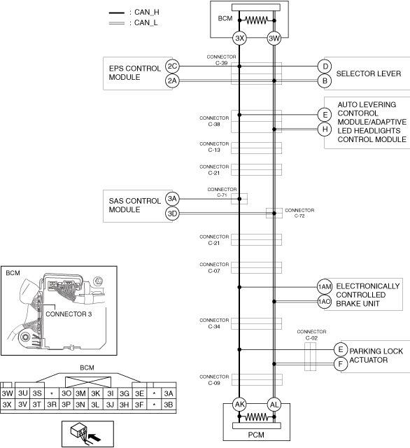
DETERMINING SHORT TO POWER SUPPLY LOCATION (CAN-BUS No.1) [R.H.D.]
id100226001900
System Wiring Diagram
a30zzw00006547
|
Determination Procedure
|
Step |
Inspection |
Action |
|
|---|---|---|---|
|
1
|
INSPECT CAN LINE BETWEEN BODY CONTROL MODULE (BCM) AND CONNECTOR C-39 FOR SHORT TO POWER SUPPLY
• Switch the main power OFF.
• Disconnect the negative lead-acid battery terminal.
• Disconnect the connector C-39.
• Connect the negative lead-acid battery terminal.
• Switch the main power ON (READY off).
• Measure the voltage at body control module (BCM) terminals 3X and 3W.
• Is the voltage between 1.5—3.5 V?
|
Yes
|
Go to Step 3.
|
|
No
|
Go to the next step.
|
||
|
2
|
INSPECT BODY CONTROL MODULE (BCM) FOR SHORT TO POWER SUPPLY
• Switch the main power OFF.
• Disconnect the negative lead-acid battery terminal.
• Disconnect the connector 3 which has body control module (BCM) terminals 3X and 3W.
• Connect the connector C-39.
• Connect the negative lead-acid battery terminal.
• Switch the main power ON (READY off).
• Measure the voltage at body control module (BCM) terminals 3X and 3W (wiring harness side).
• Is the voltage between 1.5—3.5 V?
|
Yes
|
Replace the body control module (BCM) because there is a short to the power supply in the body control module (BCM).
|
|
No
|
Repair or replace the wiring harness between the connector C-39 and body control module (BCM) because the wiring harness is shorted to the power supply.
|
||
|
3
|
INSPECT CAN LINE BETWEEN EPS CONTROL MODULE AND CONNECTOR C-39 FOR SHORT TO POWER SUPPLY
• Measure the voltage at EPS control module terminals 2C and 2A.
• Is the voltage between 1.5—3.5 V?
|
Yes
|
Go to Step 5.
|
|
No
|
Go to the next step.
|
||
|
4
|
INSPECT EPS CONTROL MODULE FOR SHORT TO POWER SUPPLY
• Switch the main power OFF.
• Disconnect the negative lead-acid battery terminal.
• Disconnect the EPS control module connector.
• Connect the connector C-39.
• Connect the negative lead-acid battery terminal.
• Switch the main power ON (READY off).
• Measure the voltage at body control module (BCM) terminals 3X and 3W.
• Is the voltage between 1.5—3.5 V?
|
Yes
|
Replace the EPS control module because there is a short to the power supply in the EPS control module.
|
|
No
|
Repair or replace the wiring harness between the EPS control module and connector C-39 because the wiring harness is shorted to the power supply.
|
||
|
5
|
INSPECT CAN LINE BETWEEN SELECTOR LEVER AND CONNECTOR C-39 FOR SHORT TO POWER SUPPLY
• Measure the voltage at selector lever terminals D and B.
• Is the voltage between 1.5—3.5 V?
|
Yes
|
Go to Step 7.
|
|
No
|
Go to the next step.
|
||
|
6
|
INSPECT SELECTOR LEVER FOR SHORT TO POWER SUPPLY
• Switch the main power OFF.
• Disconnect the negative lead-acid battery terminal.
• Disconnect the selector lever connector.
• Connect the connector C-39.
• Connect the negative lead-acid battery terminal.
• Switch the main power ON (READY off).
• Measure the voltage at body control module (BCM) terminals 3X and 3W.
• Is the voltage between 1.5—3.5 V?
|
Yes
|
Replace the selector lever because there is a short to the power supply in the selector lever.
|
|
No
|
Repair or replace the wiring harness between the selector lever and connector C-39 because the wiring harness is shorted to the power supply.
|
||
|
7
|
INSPECT CAN LINE BETWEEN CONNECTOR C-39 AND CONNECTOR C-38 FOR SHORT TO POWER SUPPLY
• Switch the main power OFF.
• Disconnect the negative lead-acid battery terminal.
• Disconnect the connector C-38.
• Connect the connector C-39.
• Connect the negative lead-acid battery terminal.
• Switch the main power ON (READY off).
• Measure the voltage at body control module (BCM) terminals 3X and 3W.
• Is the voltage between 1.5—3.5 V?
|
Yes
|
Go to the next step.
|
|
No
|
Repair or replace the wiring harness between the connector C-38 and connector C-39 because the wiring harness is shorted to the power supply.
|
||
|
8
|
INSPECT CAN LINE BETWEEN AUTO LEVELING CONTROL MODULE / ADAPTIVE LED HEADLIGHTS CONTROL MODULE AND CONNECTOR C-38 FOR SHORT TO POWER SUPPLY
• Measure the voltage at auto leveling control module / adaptive LED headlights control module terminals E and H.
• Is the voltage between 1.5—3.5 V?
|
Yes
|
Go to Step 10.
|
|
No
|
Go to the next step.
|
||
|
9
|
INSPECT AUTO LEVELING CONTROL MODULE / ADAPTIVE LED HEADLIGHTS CONTROL MODULE FOR SHORT TO POWER SUPPLY
• Switch the main power OFF.
• Disconnect the negative lead-acid battery terminal.
• Disconnect the auto leveling control module / adaptive LED headlights control module connector.
• Connect the connector C-38.
• Connect the negative lead-acid battery terminal.
• Switch the main power ON (READY off).
• Measure the voltage at body control module (BCM) terminals 3X and 3W.
• Is the voltage between 1.5—3.5 V?
|
Yes
|
Replace the auto leveling control module / adaptive LED headlights control module because there is a short to the power supply in the auto leveling control module / adaptive LED headlights control module.
|
|
No
|
Repair or replace the wiring harness between the auto leveling control module / adaptive LED headlights control module and connector C-38 because the wiring harness is shorted to the power supply.
|
||
|
10
|
INSPECT CAN LINE BETWEEN CONNECTOR C-13 AND CONNECTOR C-38 FOR SHORT TO POWER SUPPLY
• Switch the main power OFF.
• Disconnect the negative lead-acid battery terminal.
• Disconnect the connector C-13.
• Connect the connector C-38.
• Connect the negative lead-acid battery terminal.
• Switch the main power ON (READY off).
• Measure the voltage at body control module (BCM) terminals 3X and 3W.
• Is the voltage between 1.5—3.5 V?
|
Yes
|
Go to the next step.
|
|
No
|
Repair or replace the wiring harness between the connector C-38 and connector C-13 because the wiring harness is shorted to the power supply.
|
||
|
11
|
INSPECT CAN LINE BETWEEN CONNECTOR C-21 AND CONNECTOR C-13 FOR SHORT TO POWER SUPPLY
• Switch the main power OFF.
• Disconnect the negative lead-acid battery terminal.
• Connect the connector C-13.
• Disconnect the connector C-21.
• Connect the negative lead-acid battery terminal.
• Switch the main power ON (READY off).
• Measure the voltage at body control module (BCM) terminals 3X and 3W.
• Is the voltage between 1.5—3.5 V?
|
Yes
|
Go to the next step.
|
|
No
|
Repair or replace the wiring harness between the connector C-21 and connector C-13 because the wiring harness is shorted to the power supply.
|
||
|
12
|
INSPECT CAN LINE BETWEEN CONNECTOR C-21 AND CONNECTORS C-71, C-72 FOR SHORT TO POWER SUPPLY
• Switch the main power OFF.
• Disconnect the negative lead-acid battery terminal.
• Disconnect the connectors C-71, C-72.
• Connect the connector C-21.
• Connect the negative lead-acid battery terminal.
• Switch the main power ON (READY off).
• Measure the voltage at body control module (BCM) terminals 3X and 3W.
• Is the voltage between 1.5—3.5 V?
|
Yes
|
Go to the next step.
|
|
No
|
Repair or replace the wiring harness between connector C-21 and connectors C-71, C-72 because the wiring harness is shorted to the power supply.
|
||
|
13
|
INSPECT CAN LINE BETWEEN CONNECTORS C-71, C-72 AND PCM FOR SHORT TO POWER SUPPLY
• Measure the voltage at PCM terminals AK and AL.
• Is the voltage between 1.5—3.5 V?
|
Yes
|
Go to the next step.
|
|
No
|
Go to Step 15.
|
||
|
14
|
INSPECT SAS CONTROL MODULE FOR SHORT TO POWER SUPPLY
• Switch the main power OFF.
• Disconnect the negative lead-acid battery terminal.
• Disconnect the SAS control module connector.
• Connect the negative lead-acid battery terminal.
• Switch the main power ON (READY off).
• Inspect for continuity between SAS control module terminals 3A and 3D (wiring harness side).
• Is the voltage 0 V?
|
Yes
|
Replace the SAS control module connector because there is a short to the power supply in the SAS control module connector.
|
|
No
|
Repair or replace the wiring harness between the SAS control module and connectors C-71, C-72 because the wiring harness is shorted to the power supply.
|
||
|
15
|
INSPECT CAN LINE BETWEEN CONNECTOR C-21 AND CONNECTORS C-71, C-72 FOR SHORT TO POWER SUPPLY
• Switch the main power OFF.
• Disconnect the negative lead-acid battery terminal.
• Connect the connectors C-71, C-72.
• Connect the negative lead-acid battery terminal.
• Switch the main power ON (READY off).
• Measure the voltage at body control module (BCM) terminals 3X and 3W.
• Is the voltage between 1.5—3.5 V?
|
Yes
|
Go to the next step.
|
|
No
|
Repair or replace the wiring harness between connector C-21 and connectors C-71, C-72 because the wiring harness is shorted to the power supply.
|
||
|
16
|
INSPECT CAN LINE BETWEEN CONNECTOR C-07 AND CONNECTOR C-21 FOR SHORT TO POWER SUPPLY
• Switch the main power OFF.
• Disconnect the negative lead-acid battery terminal.
• Disconnect the connector C-07.
• Connect the negative lead-acid battery terminal.
• Switch the main power ON (READY off).
• Measure the voltage at body control module (BCM) terminals 3X and 3W.
• Is the voltage between 1.5—3.5 V?
|
Yes
|
Go to the next step.
|
|
No
|
Repair or replace the wiring harness between the connector C-07 and connector C-21 because the wiring harness is shorted to the power supply.
|
||
|
17
|
INSPECT CAN LINE BETWEEN CONNECTOR C-07 AND CONNECTOR C-34 FOR SHORT TO POWER SUPPLY
• Switch the main power OFF.
• Disconnect the negative lead-acid battery terminal.
• Disconnect the connector C-34.
• Connect the connector C-07.
• Connect the negative lead-acid battery terminal.
• Switch the main power ON (READY off).
• Measure the voltage at electronically controlled brake unit terminals 1AM and 1AO.
• Is the voltage between 1.5—3.5 V?
|
Yes
|
Go to the next step.
|
|
No
|
Repair or replace the wiring harness between the connector C-07 and connector C-34 because the wiring harness is shorted to the power supply.
|
||
|
18
|
INSPECT ELECTRONICALLY CONTROLLED BRAKE UNIT FOR SHORT TO POWER SUPPLY
• Switch the main power OFF.
• Disconnect the negative lead-acid battery terminal.
• Disconnect the electronically controlled brake unit connector.
• Connect the connector C-34.
• Connect the connector C-07.
• Connect the negative lead-acid battery terminal.
• Switch the main power ON (READY off).
• Measure the voltage at body control module (BCM) terminals 3X and 3W.
• Is the voltage between 1.5—3.5 V?
|
Yes
|
Replace the electronically controlled brake unit because there is a short to the power supply in the electronically controlled brake unit.
|
|
No
|
Repair or replace the wiring harness between the electronically controlled brake unit and connector C-07, connector C-34 because the wiring harness is shorted to the power supply.
|
||
|
19
|
INSPECT CAN LINE BETWEEN CONNECTOR PARKING LOCK ACTUATOR AND CONNECTOR C-34 / CONNECTOR C-09 FOR SHORT TO POWER SUPPLY
• Switch the main power OFF.
• Disconnect the negative lead-acid battery terminal.
• Disconnect the connector C-09.
• Connect the connector C-34.
• Connect the negative lead-acid battery terminal.
• Switch the main power ON (READY off).
• Measure the voltage at body control module (BCM) terminals 3X and 3W.
• Is the voltage between 1.5—3.5 V?
|
Yes
|
Go to the next step.
|
|
No
|
Go to Step 22.
|
||
|
20
|
INSPECT CAN LINE BETWEEN CONNECTOR C-09 AND CONNECTOR C-34 / CONNECTOR C-02 FOR SHORT TO POWER SUPPLY
• Switch the main power OFF.
• Disconnect the negative lead-acid battery terminal.
• Disconnect the connector C-02.
• Connect the negative lead-acid battery terminal.
• Switch the main power ON (READY off).
• Measure the voltage at body control module (BCM) terminals 3X and 3W.
• Is the voltage between 1.5—3.5 V?
|
Yes
|
Go to the next step.
|
|
No
|
Repair or replace the wiring harness between the connector C-09 and connector C-34 and connector C-02 because the wiring harness is shorted to the power supply.
|
||
|
21
|
INSPECT PARKING LOCK ACTUATOR FOR SHORT TO POWER SUPPLY
• Switch the main power OFF.
• Disconnect the negative lead-acid battery terminal.
• Disconnect the parking lock actuator connector.
• Connect the connector C-02.
• Connect the negative lead-acid battery terminal.
• Switch the main power ON (READY off).
• Measure the voltage at body control module (BCM) terminals 3X and 3W.
• Is the voltage between 1.5—3.5 V?
|
Yes
|
Replace the parking lock actuator because there is a short to the power supply in the parking lock actuator.
|
|
No
|
Repair or replace the wiring harness between the parking lock actuator and connector C-02 because the wiring harness is shorted to the power supply.
|
||
|
22
|
INSPECT PCM FOR SHORT TO POWER SUPPLY
• Switch the main power OFF.
• Disconnect the negative lead-acid battery terminal.
• Disconnect the PCM connector.
• Connect the connector C-09.
• Connect the negative lead-acid battery terminal.
• Switch the main power ON (READY off).
• Measure the voltage at body control module (BCM) terminals 3X and 3W.
• Is the voltage between 1.5—3.5 V?
|
Yes
|
Replace the PCM because there is a short to the power supply in the PCM.
(See PCM REMOVAL/INSTALLATION.)
|
|
No
|
Repair or replace the wiring harness between the PCM and connector C-09 because the wiring harness is shorted to the power supply.
|
||