 |
a30zzw00006559
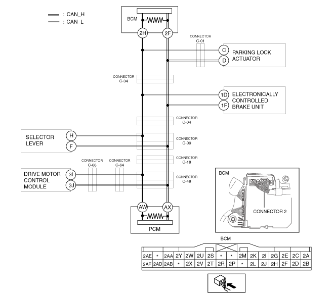
DETERMINING SHORT TO POWER SUPPLY LOCATION (CAN-BUS No.2) [R.H.D.]
id100226002300
High Voltage Part Inspection And Removal/Installation Notes
System Wiring Diagram
a30zzw00006559
|
Determination Procedure
|
Step |
Inspection |
Action |
|
|---|---|---|---|
|
1
|
INSPECT BODY CONTROL MODULE (BCM) FOR SHORT TO POWER SUPPLY
• Switch the main power OFF.
• Disconnect the negative lead-acid battery terminal.
• Disconnect the connector 2 which has body control module (BCM) terminals 2H and 2F.
• Connect the connector C-34.
• Connect the negative lead-acid battery terminal.
• Switch the main power ON (READY off).
• Measure the voltage at body control module (BCM) terminals 2H and 2F (wiring harness side).
• Is the voltage between 1.5—3.5 V?
|
Yes
|
Replace the body control module (BCM) because there is a short to the power supply in the body control module (BCM).
|
|
No
|
Go to the next step.
|
||
|
2
|
INSPECT CAN LINE BETWEEN BODY CONTROL MODULE (BCM) AND CONNECTOR C-34 FOR SHORT TO POWER SUPPLY
• Switch the main power OFF.
• Disconnect the negative lead-acid battery terminal.
• Disconnect the connector C-34.
• Connect the negative lead-acid battery terminal.
• Switch the main power ON (READY off).
• Is the voltage between 1.5—3.5 V?
|
Yes
|
Go to Step 5.
|
|
No
|
Go to the next step.
|
||
|
3
|
INSPECT CAN LINE BETWEEN PARKING LOCK ACTUATOR AND CONNECTOR C-01
• Switch the main power OFF.
• Disconnect the negative lead-acid battery terminal.
• Disconnect the connector C-01.
• Connect the negative lead-acid battery terminal.
• Switch the main power ON (READY off).
• Measure the voltage at body control module (BCM) terminals 2H and 2F.
• Is the voltage between 1.5—3.5 V?
|
Yes
|
Go to the next step.
|
|
No
|
Repair or replace the wiring harness between the body control module (BCM), connector C-34 and connector C-01 because the wiring harness is shorted to the power supply.
|
||
|
4
|
INSPECT PARKING LOCK ACTUATOR FOR SHORT TO POWER SUPPLY
• Switch the main power OFF.
• Disconnect the negative lead-acid battery terminal.
• Disconnect the parking lock actuator connector.
• Connect the connector C-01.
• Connect the negative lead-acid battery terminal.
• Switch the main power ON (READY off).
• Measure the voltage at body control module (BCM) terminals 2H and 2F.
• Is the voltage between 1.5—3.5 V?
|
Yes
|
Replace the parking lock actuator because there is a short to the power supply in the parking lock actuator.
|
|
No
|
Repair or replace the wiring harness between the parking lock actuator and connector C-01 because the wiring harness is shorted to the power supply.
|
||
|
5
|
INSPECT CAN LINE BETWEEN CONNECTOR C-34 AND CONNECTOR C-04 FOR SHORT TO POWER SUPPLY
• Switch the main power OFF.
• Disconnect the negative lead-acid battery terminal.
• Disconnect the connector C-04.
• Connect the connector C-34.
• Connect the negative lead-acid battery terminal.
• Switch the main power ON (READY off).
• Measure the voltage at body control module (BCM) terminals 2H and 2F.
• Is the voltage between 1.5—3.5 V?
|
Yes
|
Go to Step 7.
|
|
No
|
Go to the next step.
|
||
|
6
|
INSPECT ELECTRONICALLY CONTROLLED BRAKE UNIT FOR SHORT TO POWER SUPPLY
• Switch the main power OFF.
• Disconnect the negative lead-acid battery terminal.
• Disconnect the electronically controlled brake unit connector.
• Connect the connector C-04.
• Connect the negative lead-acid battery terminal.
• Switch the main power ON (READY off).
• Measure the voltage at body control module (BCM) terminals 2H and 2F.
• Is the voltage between 1.5—3.5 V?
|
Yes
|
Replace the electronically controlled brake unit because there is a short to the power supply in the electronically controlled brake unit.
|
|
No
|
Repair or replace the wiring harness between the electronically controlled brake unit and connector C-04 and connector C-34 because the wiring harness is shorted to the power supply.
|
||
|
7
|
INSPECT CAN LINE BETWEEN CONNECTOR C-34 AND CONNECTOR C-04 FOR SHORT TO POWER SUPPLY
• Switch the main power OFF.
• Disconnect the negative lead-acid battery terminal.
• Disconnect the connector C-04.
• Connect the connector C-34.
• Connect the negative lead-acid battery terminal.
• Switch the main power ON (READY off).
• Measure the voltage at body control module (BCM) terminals 2H and 2F.
• Is the voltage between 1.5—3.5 V?
|
Yes
|
Go to the next step.
|
|
No
|
Repair or replace the wiring harness between the connector C-04 and connector C-34 because the wiring harness is shorted to the power supply.
|
||
|
8
|
INSPECT CAN LINE BETWEEN CONNECTOR C-04 AND CONNECTOR C-39 FOR SHORT TO POWER SUPPLY
• Switch the main power OFF.
• Disconnect the negative lead-acid battery terminal.
• Disconnect the connector C-39.
• Connect the connector C-04.
• Connect the negative lead-acid battery terminal.
• Switch the main power ON (READY off).
• Measure the voltage at body control module (BCM) terminals 2H and 2F.
• Is the voltage between 1.5—3.5 V?
|
Yes
|
Go to the next step.
|
|
No
|
Repair or replace the wiring harness between the connector C-04 and connector C-39 because the wiring harness is shorted to the power supply.
|
||
|
9
|
INSPECT CAN LINE BETWEEN SELECTOR LEVER AND CONNECTOR C-39 FOR SHORT TO POWER SUPPLY
• Measure the voltage at selector lever terminals H and F.
• Is the voltage between 1.5—3.5 V?
|
Yes
|
Go to Step 11.
|
|
No
|
Go to the next step.
|
||
|
10
|
INSPECT SELECTOR LEVER FOR SHORT TO POWER SUPPLY
• Switch the main power OFF.
• Disconnect the negative lead-acid battery terminal.
• Disconnect the selector lever connector.
• Connect the connector C-39.
• Connect the negative lead-acid battery terminal.
• Switch the main power ON (READY off).
• Measure the voltage at body control module (BCM) terminals 2H and 2F.
• Is the voltage between 1.5—3.5 V?
|
Yes
|
Replace the selector lever because there is a short to the power supply in the selector lever.
|
|
No
|
Repair or replace the wiring harness between the selector lever and connector C-39 because the wiring harness is shorted to the power supply.
|
||
|
11
|
INSPECT CAN LINE BETWEEN CONNECTOR C-39 AND CONNECTOR C-18 FOR SHORT TO POWER SUPPLY
• Switch the main power OFF.
• Disconnect the negative lead-acid battery terminal.
• Disconnect the connector C-18.
• Connect the connector C-39.
• Connect the negative lead-acid battery terminal.
• Switch the main power ON (READY off).
• Measure the voltage at body control module (BCM) terminals 2H and 2F.
• Is the voltage between 1.5—3.5 V?
|
Yes
|
Go to the next step.
|
|
No
|
Repair or replace the wiring harness between the connector C-39 and connector C-18 because the wiring harness is shorted to the power supply.
|
||
|
12
|
INSPECT CAN LINE BETWEEN CONNECTOR C-18 AND CONNECTOR C-48 FOR SHORT TO POWER SUPPLY
• Switch the main power OFF.
• Disconnect the negative lead-acid battery terminal.
• Disconnect the connector C-48.
• Connect the connector C-18.
• Connect the negative lead-acid battery terminal.
• Switch the main power ON (READY off).
• Measure the voltage at body control module (BCM) terminals 2H and 2F.
• Is the voltage between 1.5—3.5 V?
|
Yes
|
Go to the next step.
|
|
No
|
Repair or replace the wiring harness between the connector C-48 and connector C-18 because the wiring harness is shorted to the power supply.
|
||
|
13
|
INSPECT CAN LINE BETWEEN PCM AND CONNECTOR C-48 FOR SHORT TO POWER SUPPLY
• Measure the voltage at PCM terminals AW and AX.
• Is the voltage between 1.5—3.5 V?
|
Yes
|
Go to the next step.
|
|
No
|
Go to Step 17.
|
||
|
14
|
INSPECT CAN LINE BETWEEN CONNECTOR C-48 AND CONNECTOR C-64 FOR SHORT TO POWER SUPPLY
• Switch the main power OFF.
• Disconnect the negative lead-acid battery terminal.
• Disconnect the connector C-64.
• Connect the connector C-48.
• Connect the negative lead-acid battery terminal.
• Switch the main power ON (READY off).
• Measure the voltage at body control module (BCM) terminals 2H and 2F.
• Is the voltage between 1.5—3.5 V?
|
Yes
|
Go to the next step.
|
|
No
|
Repair or replace the wiring harness between the connector C-64 and connector C-48 because the wiring harness is shorted to the power supply.
|
||
|
15
|
INSPECT CAN LINE BETWEEN CONNECTOR C-64 AND CONNECTOR C-66 FOR SHORT TO POWER SUPPLY
• Switch the main power OFF.
• Disconnect the negative lead-acid battery terminal.
• Disconnect the connector C-64.
• Connect the connector C-66.
• Connect the negative lead-acid battery terminal.
• Switch the main power ON (READY off).
• Measure the voltage at body control module (BCM) terminals 2H and 2F.
• Is the voltage between 1.5—3.5 V?
|
Yes
|
Go to the next step.
|
|
No
|
Repair or replace the wiring harness between the connector C-64 and connector C-66 because the wiring harness is shorted to the power supply.
|
||
|
16
|
INSPECT DRIVE MOTOR CONTROL MODULE FOR SHORT TO POWER SUPPLY
• Switch the main power OFF.
• Disconnect the negative lead-acid battery terminal.
• Disconnect the drive motor control module connector.
• Connect the connector C-66.
• Connect the negative lead-acid battery terminal.
• Switch the main power ON (READY off).
• Measure the voltage at body control module (BCM) terminals 2H and 2F.
• Is the voltage between 1.5—3.5 V?
|
Yes
|
Replace the drive motor control module connector because there is a short to the power supply in the drive motor control module connector.
|
|
No
|
Repair or replace the wiring harness between the drive motor control module and connector C-66 because the wiring harness is shorted to the power supply.
|
||
|
17
|
INSPECT PCM FOR SHORT TO POWER SUPPLY
• Switch the main power OFF.
• Disconnect the negative lead-acid battery terminal.
• Disconnect the PCM connector.
• Connect the connector C-48.
• Connect the negative lead-acid battery terminal.
• Switch the main power ON (READY off).
• Measure the voltage at body control module (BCM) terminals 2H and 2F.
• Is the voltage between 1.5—3.5 V?
|
Yes
|
Replace the PCM because there is a short to the power supply in the PCM.
(See PCM REMOVAL/INSTALLATION.)
|
|
No
|
Repair or replace the wiring harness between the PCM and connector C-48 because the wiring harness is shorted to the power supply.
|
||