360°VIEW MONITOR SYSTEM
id151000004300
Outline
• The 360°view monitor system is technology created from Mazda's safety philosophy stated as the reduction of accident occurrence risk itself, and which is particular to the recognition support function.
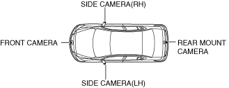
• The 360°view monitor system displays the images shot by the four cameras (front camera, side cameras (LH, RH), rear mount camera) equipped to the vehicle at the viewpoints from the front/back, left/right, and above the vehicle on the center display, and supports the driver in recognizing risks in the driver's blind spot areas under the following conditions.
-
― When entering T-intersections
― When making left/right turns
― When accelerating vehicle after parking or stopping vehicle
― When vehicles pass each other on narrow lane roads
― When parallel parking
― When reversing
• The 360°view monitor system displays flat images with little distortion on the center display so that the driver can easily recognize the location of an object or the distance to it. In addition, the flat images with little distortion are the result of particularly focusing on visually natural appearance and effective presentation, elaborately developed based on the characteristics of the human eye and brain.
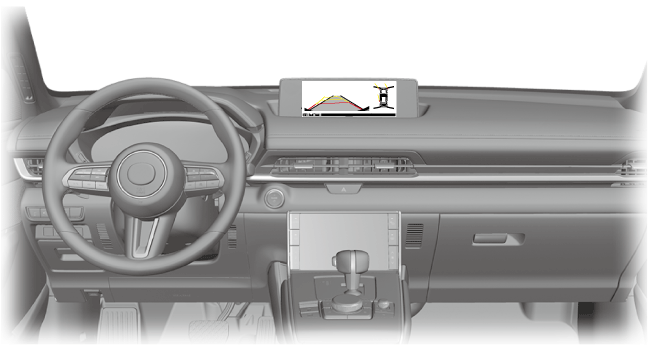
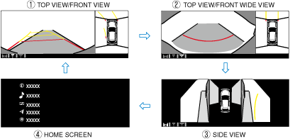
• The 360°view monitor system has 5 screen display patterns for the top view/front view, top view/rear view, top view/front wide view, top view/rear wide view, and side view. Each screen display pattern can be switched by pressing the 360°view monitor switch.
Structural view
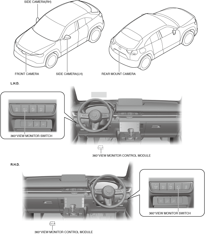
• The 360°view monitor system consists of the following parts.
-
Function
• The 360°view monitor system consists of the following functions.
Top view
-
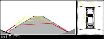
• The top view assists the driver in checking the area around the vehicle while the vehicle is moving forward or reversing, and combines video signals from the four cameras (front camera, side cameras (LH, RH), rear mount camera) equipped to the vehicle and displays the viewpoint of the area around the vehicle from the top of the vehicle on the center display.
• The top view displays on the left side of the screen when the screen of the front view, front wide view, rear view, or rear wide view is being displayed.
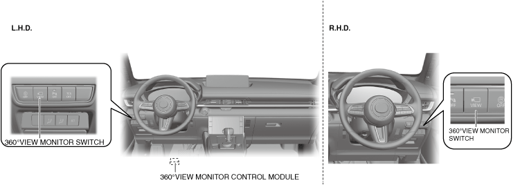
L.H.D.
R.H.D.
Front view
-
• The front view assists the driver in checking the vehicle front while the vehicle is moving forward, and displays images shot by the front camera equipped to the vehicle on the center display.
• The front view displays on the right side of the screen when the screen of the top view is being displayed.
L.H.D.
R.H.D.
Front wide view
-
• The front wide view assists the driver in checking the vehicle front and the sides of the vehicle while the vehicle is moving forward, and displays images shot by the front camera equipped to the vehicle on the center display.
• The front wide view displays wider angle images than the front view on the right side of the screen.
L.H.D.
R.H.D.
Side view
-
• The side view assists the driver in checking the left/right of the vehicle while the vehicle is moving forward, and displays images shot by the two cameras (side cameras (LH, RH)) equipped to the vehicle on the center display.
Rear view
-
• The rear view assists the driver in checking the vehicle rear while the vehicle is reversing, and displays images shot by the rear mount camera equipped to the vehicle on the center display.
• The rear view displays on the right side of the screen when the screen of the top view is being displayed.
L.H.D.
R.H.D.
Rear wide view
-
• The rear wide view assists the driver in checking the sides of the vehicle and the vehicle rear while the vehicle is reversing, and displays images shot by the rear mount camera equipped to the vehicle on the center display.
• The rear wide view displays wider angle images than the rear view on the right side of the screen.
L.H.D.
R.H.D.
Screen display function
-
• When all of the following conditions are met, the 360°view monitor system displays the 360°view monitor screen when the 360°view monitor switch is pressed or the selector lever is shifted to the R position.
-
― Switch the main power ON (READY off or on)
Screen display switching function
-
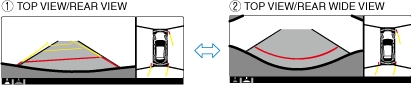
• When the 360°view monitor switch is pressed while the top view/front view, top view/rear view, top view/front wide view, top view/rear wide view, or side view is displayed, the 360°view monitor control module switches the displayed image.
When top view/front view, top view/front wide view, or side view is displayed
When top view/rear view, top view/rear wide view is displayed
Parking sensor system
-
• The parking sensor system uses ultrasonic sensors to detect obstructions around the vehicle, and notifies the driver of the approximate distance from the vehicle to the surrounding obstruction using sound and an obstruction detection indication. For details on the parking sensor system, refer to the [PARKING SENSOR SYSTEM]. (See
PARKING SENSOR SYSTEM.)
Rear cross traffic alert system
-
• The rear cross traffic alert system uses radar sensors to detect vehicles approaching from the rear of the vehicle, and assists the driver in checking the rear of the vehicle while reversing by flashing the blind spot monitoring (BSM) warning lights and activating the warning sound. For details on the rear cross traffic alert system, refer to [REAR CROSS TRAFFIC ALERT SYSTEM]. (See
REAR CROSS TRAFFIC ALERT (RCTA) SYSTEM.)
Front cross traffic alert system
-
• The front cross traffic alert system uses radar sensors to detect vehicles approaching from the left and right in the front of the vehicle when entering an area with poor visibility such as an intersection, and warns the driver by flashing the blind spot monitoring (BSM) warning lights and activating the warning sound. For details on the front cross traffic alert system, refer to [FRONT CROSS TRAFFIC ALERT SYSTEM]. (See
FRONT CROSS TRAFFIC ALERT (FCTA) SYSTEM.)
Malfunction indication function
-
• The 360°view monitor control module displays the system malfunction condition on the center display.
-
Note
-
• If each camera has a malfunction, the image taken from the applicable camera is displayed on the center display in black.
Personalization feature
-
• Refer to [PERSONALIZATION FEATURES] in the workshop manual for details on personalization features.
System conditions display
Icon display
-
• The icons displayed on the screen are as follows.
Display example
|
Icon name
|
Content
|
|
(1) View status icon
|
Indicates which image is displayed among the front view, front wide view, side view, rear view, and rear wide view.
|
|
(2) Parking sensor status icon
|
Indicates that the parking sensor has a problem or the parking sensor system is switched off.
|
Top view/front view
-
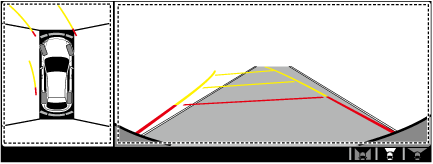
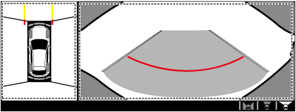
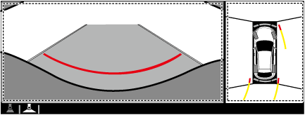
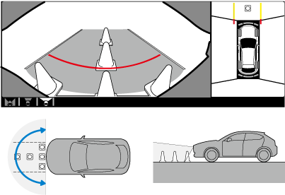
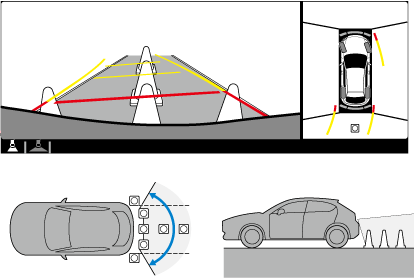
• The top view/front view displays the shooting range shown in the figure.
-
Note
-
• For the top view display, the diagonal lines at the front and rear of the vehicle image and the seams where each of the camera images merge are blind spots.
• Because images displayed on the top view screen are processed from the video from each camera, the top view display may be displayed in the following ways.
-
― If an image containing an object with a color is picked up in the wide range by any of the cameras, the top view display may be displayed in that color.
― Each seamed image may be displayed in a color tone different from the actual color tone.
― Obstructions displayed in the front view may not display on the top view screen.
― If the position or angle of each camera changes due to vehicle inclination, misaligned images may be displayed.
― Lines on the road may be misaligned at the seams of images.
― People or obstructions displayed on the screen may appear differently than in actuality. (People or obstructions may appear fallen, larger, or longer than they actually are.)
Top view/front view shooting range
Top view/front view indication
|
Display item
|
Display line color
|
Content
|
|
(1) Tire icons (steering interlocking)
|
—
|
Icons for indicating the tire directions.
|
|
(2) Projected vehicle path lines (steering interlocking)
|
Yellow, red
|
Projected vehicle path calculated from the steering angle.
• Line indicating the path where the edge of the front bumper is expected to travel
• Line indicating the path where the inner side of the vehicle is expected to travel
|
|
(3) Vehicle width extension lines (fixed)
|
Blue
|
Lines indicating the extension of the vehicle width including the power outer mirror.
|
|
(4) Projected vehicle path distance guide lines (steering interlocking)
|
Red
|
Distance reference line indicating approx. 0.5 m {19 in} from the front end of the front bumper.
|
|
Yellow
|
Distance reference line indicating approx. 1.0 m {39 in} and 2.0 m {78 in} from the front end of the front bumper.
|
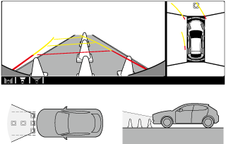
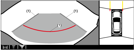
Top view/front wide view
-
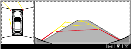
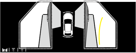
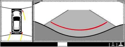
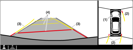
• Top view/front wide view shoots the range shown in the figure.
Top view/front wide view shooting range
Top view/front wide view display
|
Display item
|
Display line color
|
Content
|
|
(1) Distance reference line
|
Red
|
Distance reference line indicating approx.0.5 m {19 in} from the front end of the front bumper.
|
|
(2) Vehicle width extension lines
|
Blue
|
Lines indicating the extension of the vehicle width including the power outer mirror.
|
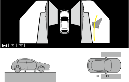
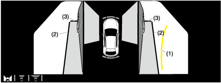
Side view
-
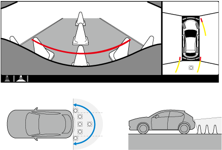
• The side view shoots the range shown in the figure.
Side view shooting range
Side view display
|
Display item
|
Display line color
|
Content
|
|
(1)PROJECTED VEHICLE PATH LINES
|
Yellow
|
Projected vehicle path calculated from steering angle
|
|
(2)VEHICLE PARALLEL GUIDE LINES
|
Blue
|
Line indicating the approximate vehicle width including the power outer mirror.
|
|
(3)VEHICLE FRONT END GUIDE LINES
|
Blue
|
Distance guide line from front end of front bumper
|
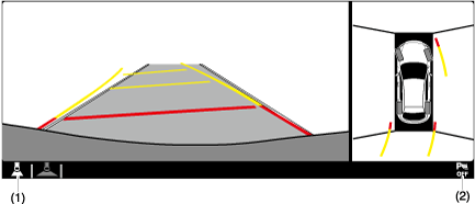
Top view/rear view
-
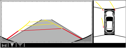
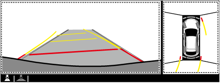
• The top view/rear view shoots the range shown in the figure.
-
Note
-
• For the top view display, the diagonal lines at the front and rear of the vehicle image and the seams where each of the camera images merge are blind spots.
• Because images displayed on the top view screen are processed from the video from each camera, the top view display may be displayed in the following ways.
-
― If an image containing an object with a color is picked up in the wide range by any of the cameras, the top view display may be displayed in that color.
― Each seamed image may be displayed in a color tone different from the actual color tone.
― Obstructions displayed in the rear view may not display on the top view screen.
― If the position or angle of each camera changes due to vehicle inclination, misaligned images may be displayed.
― Lines on the road may appear distorted at the seams where each of the camera images merge.
― People or obstructions displayed on the screen may appear differently than in actuality. (People or obstructions may appear fallen, larger, or longer than they actually are.)
Top view/rear view shooting range
Top view/rear view display
|
Display item
|
Display line color
|
Content
|
|
(1) Tire icons (steering interlocking)
|
—
|
Icons for indicating the tire directions.
|
|
(2) Projected vehicle path lines (steering interlocking)
|
Yellow, red
|
Projected vehicle path calculated from the steering angle.
• Lines indicating the paths where the rear wheels are expected to travel
• Line indicating the path where the outer side of the vehicle is expected to travel
|
|
(3) Vehicle width extension lines (fixed)
|
Blue
|
Lines indicating the extension of the vehicle width including the power outer mirror.
|
|
(4) Projected vehicle path distance reference lines (steering interlocking)
|
Red
|
Distance reference line indicating approx. 0.5 m {19 in} from the front end of the rear bumper.
|
|
Yellow
|
Distance reference line indicating approx. 1.0 m {39 in} and 2.0 m {78 in} from the front end of the rear bumper.
|
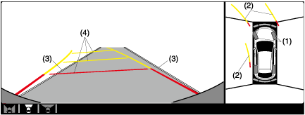
Top view/rear wide view
-
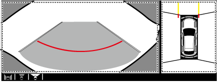
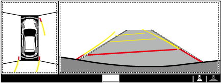
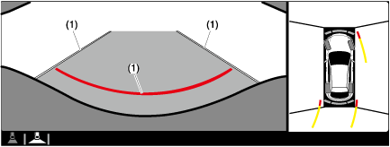
• The top view/rear wide view shoots the range shown in the figure.
Top view/rear wide view display
|
Display item
|
Display line color
|
Content
|
|
(1) Distance reference line
|
Red
|
Distance reference line indicating approx. 0.5 m {19 in} from the front end of the rear bumper.
|
|
(2) Vehicle width extension lines
|
Blue
|
Lines indicating the extension of the vehicle width including the power outer mirror.
|
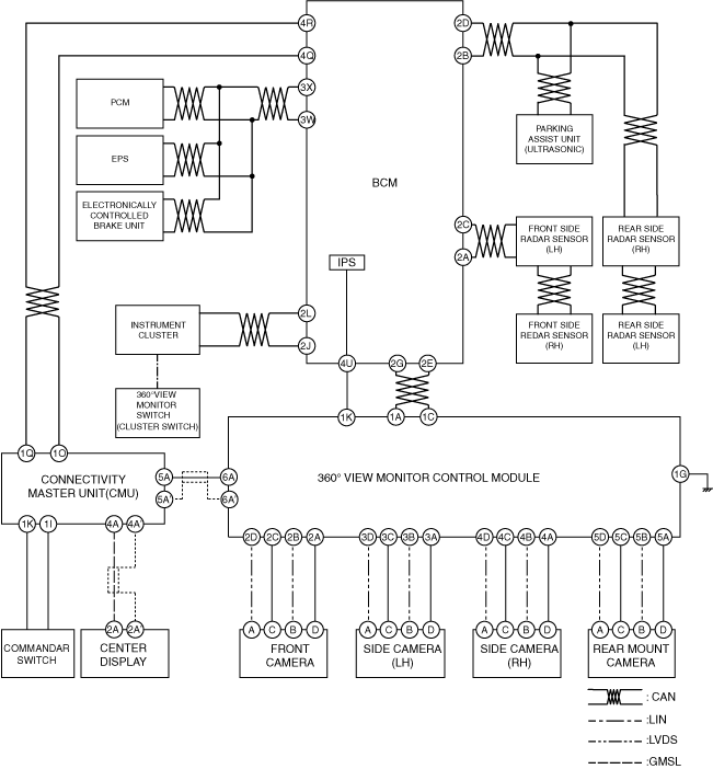
System wiring diagram
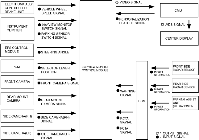
Block Diagram
Operation
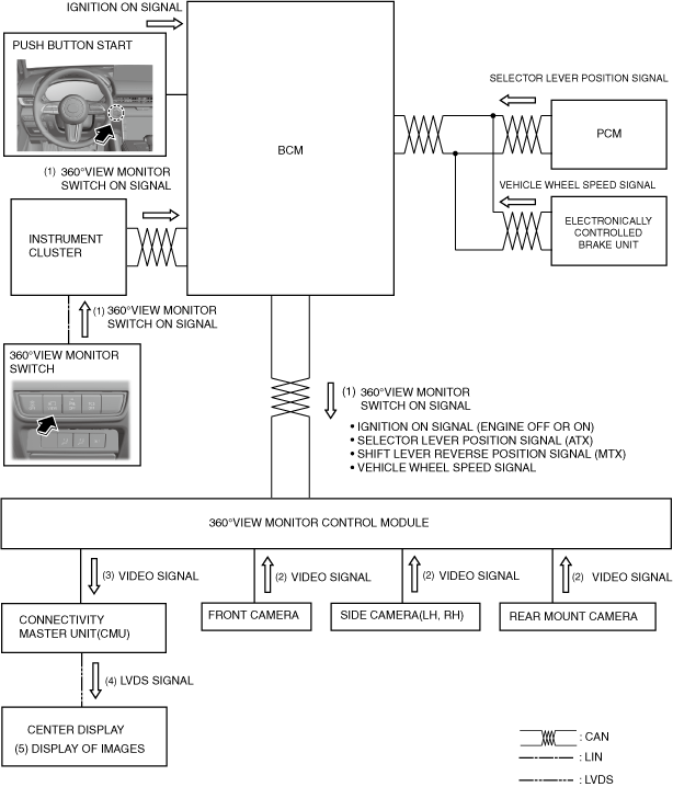
Top view/front view, top view/front wide view, side view display operation
-
Operation conditions
-
• When all of the following conditions are met, the top view/front view, top view/front wide view, and side view can be displayed.
-
― Switch the main power ON (READY off or on)
― Selector lever is in position other than R
1. When a 360°view monitor switch ON signal (1) is received with the operation conditions met, the 360°view monitor control module receives video signals (2) from the front camera/side cameras (LH, RH)/rear mount camera.
2. The 360°view monitor control module processes the received video signals into images and then sends them to the CMU (3).
3. The CMU converts the received video signals to an LVDS signal and sends (4) the LVDS signal to the center display.
4. The center display indicates (5) the images at the area around the vehicle based on the LVDS signal received from the CMU.
5. When any of the following conditions is met, the 360°view monitor control module switches the images indicated on the center display to non-display.
-
• Selector lever is shifted to P position
• When 360°view monitor switch is pressed while vehicle speed is less than approx. 15 km/h {9.3 mph}
-
― Approx. 270 s have elapsed since 360°view monitor switch was pressed
― Vehicle speed is approx. 15 km/h {9.3 mph} or more
• When 360°view monitor switch is pressed while vehicle speed is approx. 15 km/h {9.3 mph} or more
-
― Vehicle speed is approx. 15 km/h {9.3 mph} or more after approx. 8 s have elapsed since 360°view monitor switch was pressed
― Approx. 262 s have elapsed or vehicle speed exceeds 15 km/h {9.3 mph} from the point when vehicle speed was less than 15 km/h {9.3 mph} after 8 s had elapsed since pressing 360°view monitor switch
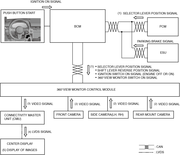
Top view/rear view, top view/rear wide view display operation
-
Operation conditions
-
• When all of the following conditions are met, the top view/rear view and the top view/rear wide view can be displayed.
-
― Main power is switched ON (READY off or on)
― Selector lever is in R position
1. When a selector lever R position signal is received (1) with the operation conditions met, the 360°view monitor control module receives video signals (2) from the front camera/side cameras (LH, RH)/rear mount camera.
2. The 360°view monitor control module processes the received video signals into images and then sends them to the CMU (3).
3. The CMU converts the received video signals to a LVDS signal (4) and sends the LVDS signal to the center display.
4. The center display indicates (5) the images at the area around the vehicle based on the LVDS signal received from the CMU.
5. When any of the following conditions is met, the 360°view monitor control module switches the images indicated on the center display to non-display.
-
• Selector lever is shifted to P position