|
1
|
RECORD VEHICLE STATUS WHEN DTC WAS DETECTED TO UTILIZE WITH REPEATABILITY VERIFICATION
• Record the snapshot data.
-
Note
-
• Recording can be facilitated using the screen capture function of the PC.
|
—
|
Go to the next step.
|
|
2
|
DETERMINE IF MALFUNCTION IS ON CHARGING EQUIPMENT SIDE
• Perform quick charging using charging equipment other than that used when the DTC was output.
• Perform the DTC inspection for the PCM.
• Is the DTC P0D0F:00 displayed?
-
Note
-
• If DTC P0D0F:00 is displayed as a past malfunction, a malfunction in the charging equipment used when the DTC was output can be considered.
|
Yes
|
Go to the next step.
|
|
No
|
The system is normal. (Explain to the customer that there is a possibility that a malfunction was detected due to a charging equipment malfunction.)
• Go to the repair completion verification 1.
|
|
3
|
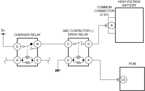
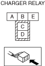
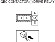
INSPECT QBC CONTACTOR (-) DRIVE RELAY FOR MALFUNCTION
• Inspect the applicable part.
• Is the part normal?
|
Yes
|
Go to the next step.
|
|
No
|
Repair or replace the malfunctioning location and perform the repair completion verification 1.
|
|
4
|
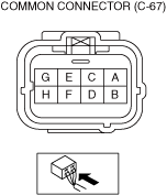
INSPECT COMMON CONNECTOR (C-67) CONNECTOR FOR MALFUNCTION
• Inspect the applicable connector and terminal.
• Are the connector and terminal normal?
|
Yes
|
Go to the next step.
|
|
No
|
Common connector (C-67) connector (high voltage battery side) malfunction:
• Replace the high voltage battery, then go to the repair completion verification 1.
Common connector (C-67) connector (vehicle wiring harness side) malfunction:
• Repair or replace the malfunctioning location and perform the repair completion verification 1.
|
|
5
|
INSPECT PCM CONNECTOR OR TERMINALS FOR MALFUNCTION
• Inspect the applicable connector and terminal.
• Are the connector and terminal normal?
|
Yes
|
Go to the next step.
|
|
No
|
Repair or replace the malfunctioning location and perform the repair completion verification 1.
|
|
6
|
INSPECT QBC CONTACTOR (-) DRIVE RELAY CONTROL CIRCUIT FOR SHORT TO POWER SUPPLY
• Inspect the applicable circuit for a short to power supply.
• Is the circuit normal?
|
Yes
|
Go to the next step.
|
|
No
|
Repair or replace the malfunctioning location and perform the repair completion verification 1.
|
|
7
|
INSPECT WIRING HARNESS BETWEEN QBC CONTACTOR (-) DRIVE RELAY AND COMMON CONNECTOR (C-67) CONNECTOR FOR SHORT TO POWER SUPPLY
• Inspect the applicable circuit for a power supply.
• Is the circuit normal?
|
Yes
|
Refer to the controller area network (CAN) malfunction diagnosis flow to inspect for a CAN communication error.
If the CAN communication is normal, perform the diagnosis from Step 1.
• If the malfunction recurs, replace the high voltage battery, then go to the repair completion verification 1.
|
|
No
|
Repair or replace the malfunctioning location and perform the repair completion verification 1.
|
|
Repair completion verification 1
|
VERIFY THAT VEHICLE IS REPAIRED
• Install/connect the part removed/disconnected during the troubleshooting procedure.
• Clear the DTC recorded in the memory.
• Replicate the vehicle conditions at the time the DTC was detected using the following procedure.
-
Warning
-
• While performing this step, always operate the vehicle in a safe and lawful manner.
• When the M-MDS is used to observe monitor system status while driving, be sure to have another technician with you, or record the data in the M-MDS using the PID/DATA MONITOR AND RECORD capturing function and inspect later.
-
― Drive the vehicle under the snapshot data condition.
• Perform the DTC inspection for the PCM.
• Is the same Pending DTC present?
|
Yes
|
Refer to the controller area network (CAN) malfunction diagnosis flow to inspect for a CAN communication error.
If the CAN communication is normal, perform the diagnosis from Step 1.
• If the malfunction recurs, replace the PCM, then go to the next step.
|
|
No
|
Go to the next step.
|
|
Repair completion verification 2
|
VERIFY IF OTHER DTCs DISPLAYED
• Perform the DTC inspection.
• Are any other DTCs displayed?
|
Yes
|
Repair the malfunctioning location according to the applicable DTC troubleshooting.
|
|
No
|
DTC troubleshooting completed.
|