|
1
|
RECORD VEHICLE STATUS WHEN DTC WAS DETECTED TO UTILIZE WITH REPEATABILITY VERIFICATION
• Record the snapshot data.
-
Note
-
• Recording can be facilitated using the screen capture function of the PC.
|
—
|
Go to the next step.
|
|
2
|
DETERMINE IF MALFUNCTION IS ON CHARGING EQUIPMENT SIDE
• Perform quick charging using charging equipment other than that used when the DTC was output.
• Perform the DTC inspection for the battery charge control module.
• Is DTC P0D27:00 displayed as a current malfunction?
-
Note
-
• If DTC P0D27:00 is displayed as a past malfunction, a malfunction in the charging equipment used when the DTC was output can be considered.
|
Yes
|
Go to the next step.
|
|
No
|
The system is normal. (Explain to the customer that there is a possibility that a malfunction was detected due to a charging equipment malfunction.)
Go to the repair completion verification 2.
|
|
3
|
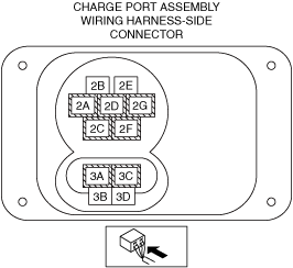
INSPECT CHARGE PORT ASSEMBLY CONNECTOR FOR MALFUNCTION
-
Warning
-
<<High voltage>>
• Wear insulated gloves when working on a high voltage system.
• Remove the service plug.
• After 10 min have elapsed after removing the service plug, perform a zero voltage verification at the voltage detection point of the junction box No.3 to verify that there is no electrical charge in the high voltage circuit.
• Inspect the applicable connector and terminal.
• Are the connector and terminal normal?
|
Yes
|
Go to the next step.
|
|
No
|
Replace the charge port assembly, then go to the repair completion verification 1.
|
|
4
|
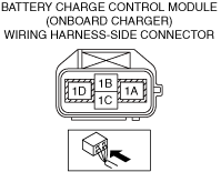
INSPECT BATTERY CHARGE CONTROL MODULE (ONBOARD CHARGER) CONNECTOR FOR MALFUNCTION
-
Warning
-
<<High voltage>>
• Wear insulated gloves when working on a high voltage system.
• Verify that the service plug is removed.
• Inspect the applicable connector and terminal.
• Are the connector and terminal normal?
|
Yes
|
Go to the next step.
|
|
No
|
Repair or replace the malfunctioning location and perform the repair completion verification 1.
|
|
5
|
INSPECT THE CONNECTION CONDITION BETWEEN BATTERY CHARGE CONTROL MODULE (ONBOARD CHARGER) AND THE HIGH VOLTAGE CABLES
-
Warning
-
<<High voltage>>
• Wear insulated gloves when working on a high voltage system.
• Verify that the service plug is removed.
• Inspect the connection condition between the high voltage battery and high voltage cables.
• Is the connection condition normal?
|
Yes
|
Go to the next step.
|
|
No
|
Repair or replace the malfunctioning location and perform the repair completion verification 1.
|
|
6
|
INSPECT FOR POOR INSULATION BETWEEN AC CHARGE CIRCUIT (+) AND AC CHARGE CIRCUIT (−) FOR BATTERY CHARGE CONTROL MODULE (ONBOARD CHARGER)
-
Warning
-
<<High voltage>>
• Wear insulated gloves when working on a high voltage system.
• Verify that the service plug is removed.
• Refer to the high voltage cable insulation inspection and inspect the following cable for poor insulation between the AC charge circuit (+) and AC charge circuit (−).
• Is the circuit normal?
|
Yes
|
Go to the next step.
|
|
No
|
Replace the high voltage cable, then go to the repair completion verification 1.
|
|
7
|
INSPECT BATTERY CHARGE CONTROL MODULE (ONBOARD CHARGER) AC CHARGE CIRCUIT (+) OR AC CHARGE CIRCUIT (−) FOR OPEN CIRCUIT
-
Warning
-
<<High voltage>>
• Wear insulated gloves when working on a high voltage system.
• Verify that the service plug is removed.
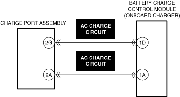
• Refer to the high voltage cable continuity inspection and inspect the continuity between the following terminals.
-
― Charge port assembly side terminal 2G—Battery charge control module (onboard charger) side terminal 1D
― Charge port assembly side terminal 2A—Battery charge control module (onboard charger) side terminal 1A
• Is the circuit normal?
|
Yes
|
Go to the next step.
|
|
No
|
Replace the high voltage cable, then go to the repair completion verification 1.
|
|
8
|
INSPECT CHARGE PORT FOR MALFUNCTION
-
Warning
-
<<High voltage>>
• Wear insulated gloves when working on a high voltage system.
• Verify that the service plug is removed.
• Inspect the applicable part.
• Is the part normal?
|
Yes
|
Go to the next step.
|
|
No
|
Replace the charge port assembry, then go to the repair completion verification 1.
|
|
9
|
INSPECT BATTERY CHARGE CONTROL MODULE (ONBOARD CHARGER) FOR MALFUNCTION DEPENDING ON REPEATABILITY
-
Warning
-
<<High voltage>>
• Wear insulated gloves when working on a high voltage system.
• Install/connect the part removed/disconnected during the troubleshooting procedure.
• Clear the DTC recorded in the memory.
• Perform quick charging using charging equipment other than that used when the DTC was output.
• Perform the DTC inspection for the Battery charge control module.
• Is DTC P0D27:00 displayed as a current malfunction?
|
Yes
|
Refer to the controller area network (CAN) malfunction diagnosis flow to inspect for a CAN communication error.
If the CAN communication is normal, perform the diagnosis from Step 1.
• If the malfunction recurs, replace the onboard charger, then go to the repair completion verification 2.
|
|
No
|
Go to the repair completion verification 2.
|
|
Repair completion verification 1
|
VERIFY THAT VEHICLE IS REPAIRED
-
Warning
-
<<High voltage>>
• Wear insulated gloves when working on a high voltage system.
• Install/connect the part removed/disconnected during the troubleshooting procedure.
• Clear the DTC recorded in the memory.
• Perform quick charging using charging equipment other than that used when the DTC was output.
• Perform the DTC inspection for the Battery charge control module.
• Is the same Pending DTC present?
|
Yes
|
Refer to the controller area network (CAN) malfunction diagnosis flow to inspect for a CAN communication error.
If the CAN communication is normal, perform the diagnosis from Step 1.
• If the malfunction recurs, replace the onboard charger, then go to the next step.
|
|
No
|
Go to the next step.
|
|
Repair completion verification 2
|
VERIFY IF OTHER DTCs DISPLAYED
• Perform the DTC inspection.
• Are any other DTCs displayed?
|
Yes
|
Repair the malfunctioning location according to the applicable DTC troubleshooting.
|
|
No
|
DTC troubleshooting completed.
|